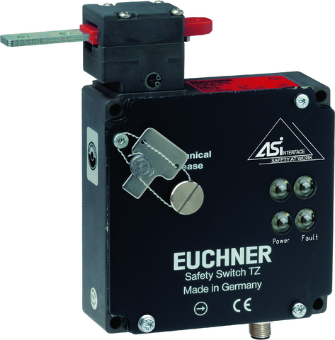
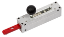
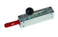
TZ1LE024SEM4AS1 (Order no. 086140)
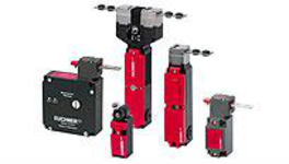
Safety switch TZ ASi, plug connector(s) M12
- AS-Interface
- Plug connector(s) M12, 4-pin
- Auxiliary release
- LED indicator
- Actuating head fitted left
- Closed-circuit current principle
Description
Approach direction
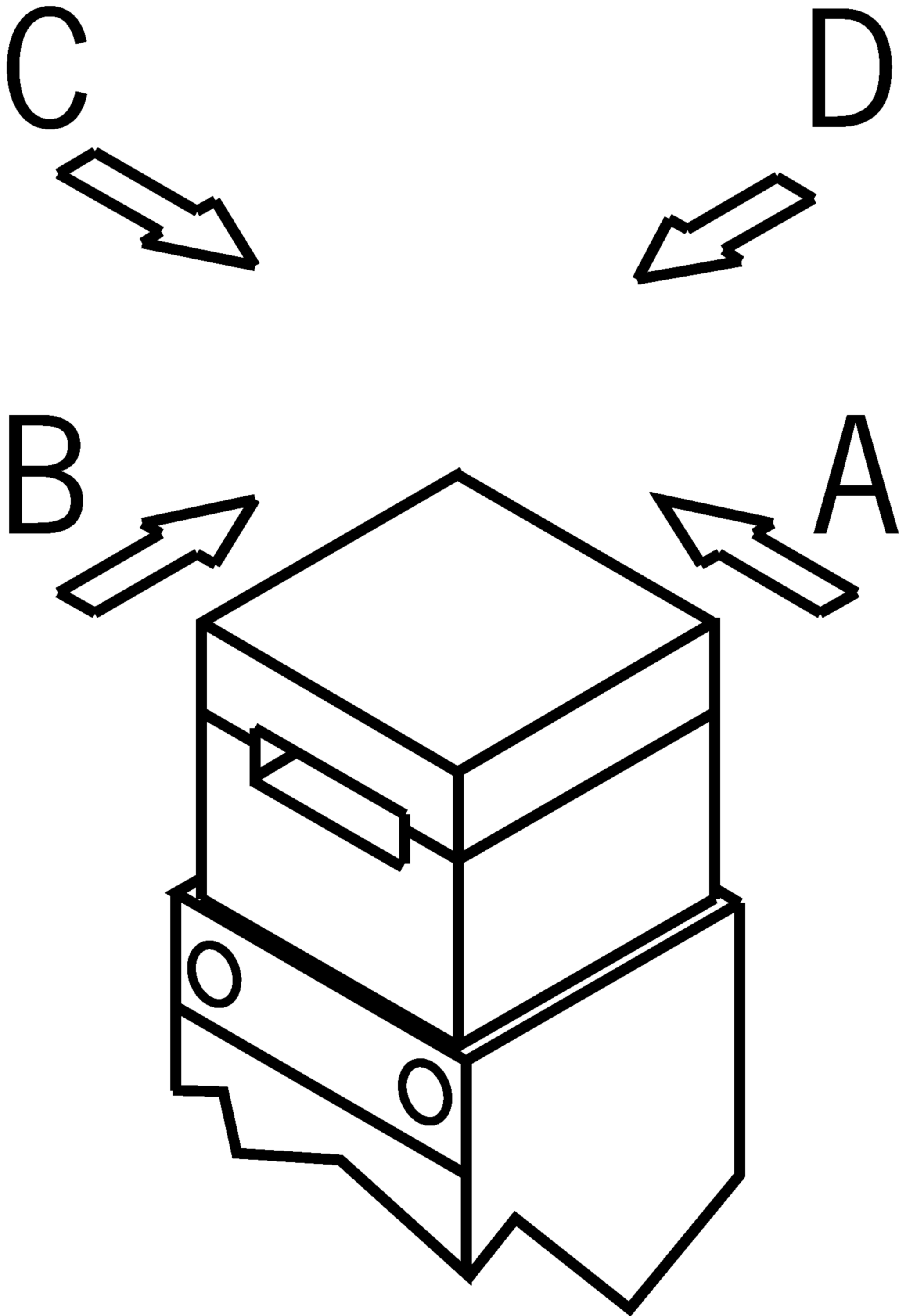
Horizontal
Can be adjusted in 90° steps
Guard locking principle
closed-circuit current (power to unlock): In a safety guard with guard locking according to the closed-circuit current principle, the guard is locked by spring force until the guard locking solenoid is supplied with current. The guard is unlocked by means of magnetic force. This is also referred to as mechanical guard locking.
Control of the guard locking solenoid
The guard locking solenoid is controlled via AS-Interface bit D0. In order to achieve safe control of the guard locking, the auxiliary voltage must also be switched safely.
auxiliary voltage
The ASi auxiliary voltage is required to supply the guard locking solenoid.
AS-Interface inputs
D0, D1 | Monitoring of the guard position |
D2, D3 | Monitoring the guard locking |
AS-Interface outputs
D0 | Activating the guard locking |
D1 | LED red |
D2 | LED green |
LED indicator
The Power LED indicates the operating voltage on the bus.
The Fault LED indicates when an error has been detected on the AS-Interface bus.
The green and red LEDs can be controlled by the control system via the bus as required using bits D1 and D2.
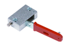
Auxiliary release
The auxiliary release on the front allows access to the machine in the event of a malfunction, e.g. a power failure. It is unlocked using a tool or a key. The auxiliary release must be secured against misuse (sealing, laking).
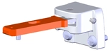
Required accessories
Actuator is not included in the scope of delivery.
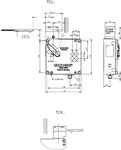
Dimensional drawings
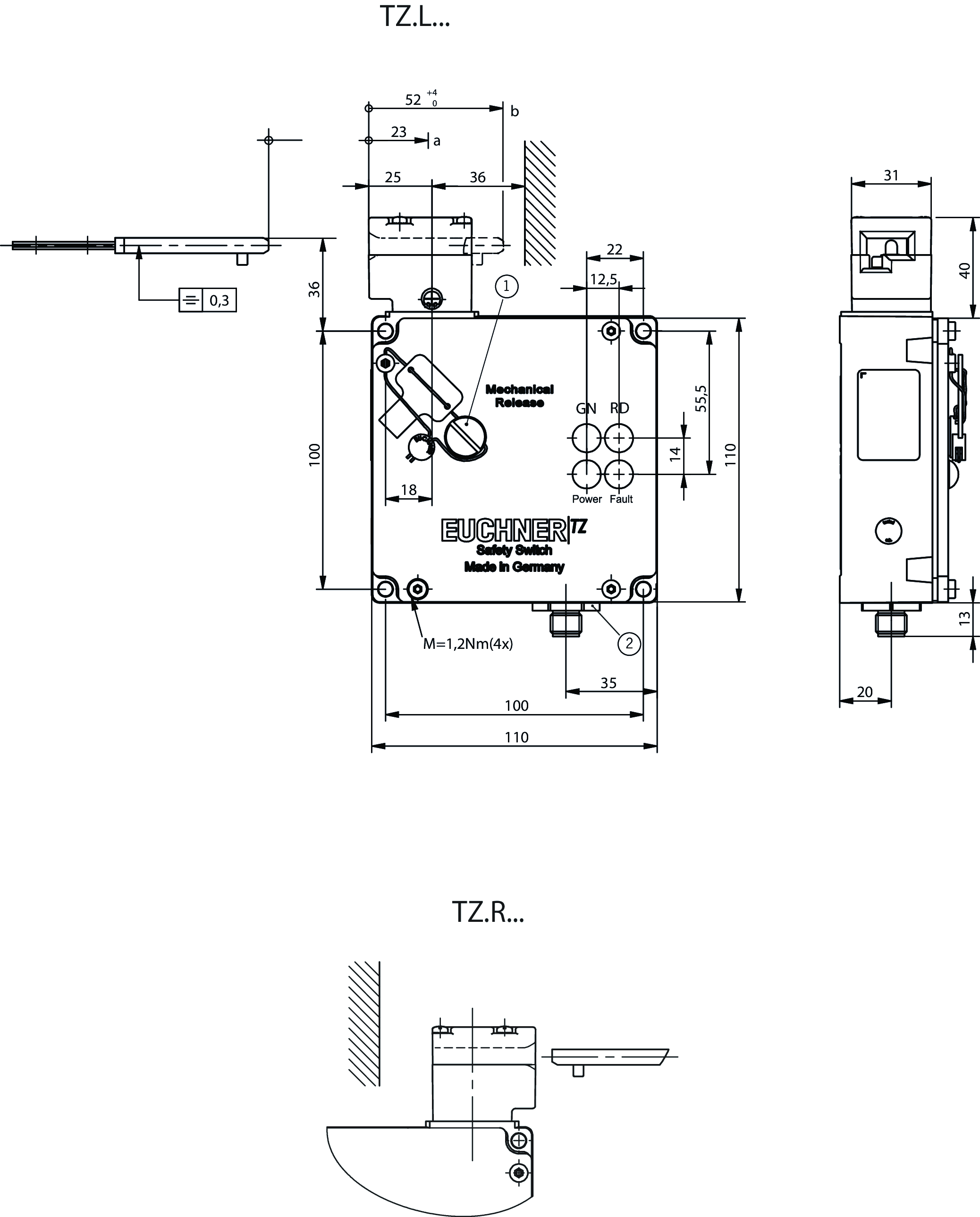
| 1 | Auxiliary release |
| 2 | Plug connector not aligned |
| a | Travel without operation: actuator is in the guide slot, but function is not triggered. |
| b | Switching operation completed. Actuator must be inserted to this point to ensure safe switching. The actuator must be withdrawn at least to point a for switching off. |
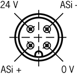
Connection examples

| View of plug side |
Technical data
Approvals


Electrical connection values
| ASI operating current | max. 45 mA |
| AS-Interface auxiliary voltage | 24 V -15 ... 10 % |
| Auxiliary current AS-Interface | 350 mA |
| AS-Interface LED | |
| green | Power |
| red | Fault |
| AS-Interface protocol | ASi-3 |
| ASI data out | D0 = control of guard locking, D1 = red LED, D2 = green LED |
| ASI data in | D0, D1 = door position, D2, D3 = guard locking |
| AS-Interface slave type | ID-Code: B, EA-Code: 7 |
| ASI voltage | 22.5 ... 30 ... 31.6 V |
| Solenoid duty cycle | 100 % |
Mechanical values and environment
| Approach speed | max. 20 m/min |
| Approach direction | |
| Actuating head left | C |
| Connection type | |
| 1 x | Plug connector M12 (4-pin) |
| Number of door position positively driven contacts | |
| according to AS-i Safety at Work | |
| Number of guard lock monitoring positively driven contacts | |
| according to AS-i Safety at Work | 1 D2,D3 (1 = locked) |
| Extraction force | 30 N |
| Actuation frequency | max. 1200 1/h |
| Actuating force | 35 N |
| Installation orientation | any |
| Insertion depth | 52 mm |
| Mechanical life | 1 x 10⁶ |
| Retention force | 10 N |
| Switching principle | Slow-action switching contact |
| Degree of protection | IP67 |
| Ambient temperature | -25 ... +55 °C |
| Material | |
| Housing | Anodized die-cast alloy |
| Contact | Silver alloy, gold flashed |
| Guard locking principle | Closed-circuit current principle |
Characteristic values according to EN ISO 13849-1 and EN IEC 62061
| B10D | Mission time | |
|---|---|---|
| Monitoring of the guard position | 3x10⁶ | 20 y |
| Important! Values valid at DC-13 100 mA/24V | ||
| Monitoring of guard locking | 3x10⁶ | 20 y |
| Important! Values valid at DC-13 100 mA/24V | ||
In combination with actuator ACTUATOR-Z-G
| Overtravel | 4 mm |
In combination with actuator ACTUATOR-Z-GN
| Overtravel | 16 mm |
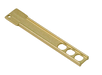
Accessories

BETAETIGER-Z-G
- Two stainless-steel safety screws per actuator
BETAETIGER-Z-G/V25
- Two stainless-steel safety screws per actuator
- Packaging unit 25 pieces

BETAETIGER-Z-GN
- Two stainless-steel safety screws per actuator

BETAETIGER-Z-GME
- Made of solid stainless steel
- Two stainless-steel safety screws per actuator


RIEGEL NZ/TZ-S1
- Bolt for safety switch NZ.VZ, NZ.VZ.VS and TZ
- Aluminum bolt
- For doors hinged on the right or left.
- Spring catch in open position
- Suitable for a door gap of approx. 15 mm
RIEGEL NZ/TZ-S2
- Bolt for safety switch NZ.VZ, NZ.VZ.VS and TZ
- Aluminum bolt
- For doors hinged on the right or left.
- Spring catch in open position
- Suitable for a door gap of approx. 15 mm

RIEGEL TZ-C-NIRO
- Stainless steel bolt
- For doors hinged on the left
- Suitable for a door gap of approx. 15 mm

RIEGEL TZ-C-NIRO-C2101
- Stainless steel bolt
- For doors hinged on the left
- Can be locked in open position with padlocks
- Actuator and switch bracket included
- Bolt for safety switch TZ
- Suitable for a door gap of approx. 15 mm


Downloads
Complete package
Download all important documents with a single click.
Content:
- The operating instructions and any additions to the operating instructions or brief instructions
- Any data sheets to supplement the operating instructions
- The declaration of conformity
Single Documents

Déclaration UE de conformité
Declaración de conformidad UE
EU-Konformitätserklärung
Dichiarazione UE di conformità

Déclaration UE de conformité
Declaración de conformidad UE
EU-Konformitätserklärung
Dichiarazione UE di conformità


Mode d’emploi Interrupteur de sécurité TZ…AS1
Betriebsanleitung Sicherheitsschalter TZ…AS1
Istruzioni di impiego Finecorsa di sicurezza TZ…AS1


Other Documents


CAD data

Ordering data
| Ordernumber | 086140 |
| Item designation | TZ1LE024SEM4AS1 |
| Gross weight | 1,199kg |
| Customs tariff number | 85365019000 |
| ECLASS | 27-27-26-03 Safety switch with guard control |
