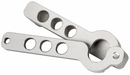
CET3-AP-CRA-AH-50X-SI-111346 (Order no. 111346)
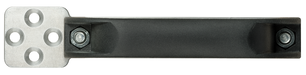
Non-contact safety switch CET-AP-..., for connection to decentralized peripheral systems
- Safety switch with guard locking and integrated evaluation electronics
- Locking force up to 6500 N
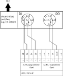
- Direct connection to decentralized peripheral systems (e.g. ET200pro)
- Short circuit monitoring
- 2 safety outputs (semiconductor outputs)
- Category 4 / PL e according to EN ISO 13849-1
- With 2 plug connectors M12
- Unicode
- Indication of the door position by LED
- Approach direction A (delivery state)
Description
Approach direction

Horizontal
Can be adjusted in 90° steps
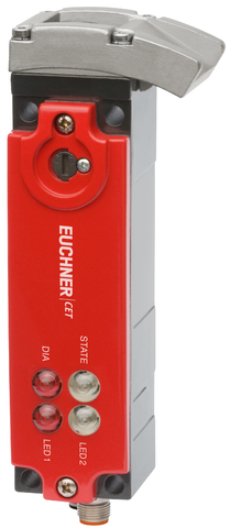
Safety switch
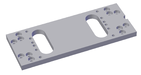
The device may be operated only in conjunction with the actuator CET-A-....
Important: The actuator must be ordered separately.
Unicode evaluation
Each actuator is highly coded (unicode). The switch detects only taught-in actuators. Additional actuators can be taught-in. Only the last actuator taught-in is detected.
Solenoid operating voltage
- DC 24 V +10%, -15%
Guard locking type
CET3 | Closed-circuit current principle, guard locking by spring force. Release by applying voltage to the guard locking solenoid. |
LED function display
State LED | Status LED |
DIA LED | Diagnostics LED |
LED 1 rd | illuminates when the solenoid is energized |
LED 2 gn | illuminates when door is closed |
Category according to EN ISO 13849-1
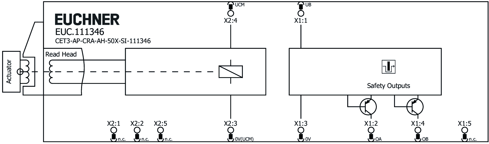
Due to two redundantly designed semiconductor outputs (safety outputs) with internal monitoring suitable for:
- Category 4 / PL e according to EN ISO 13849-1
- The stated safety characteristics apply to any installation orientations of the safety switch.
Important: To achieve the stated category in accordance with EN ISO 13849-1, both safety outputs (OA and OB) must be evaluated.
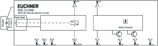
Connector assignment
| Plug connector (view of connection side) | Pin | Designation | Function | Connecting cable conductor coloring |
|---|---|---|---|---|
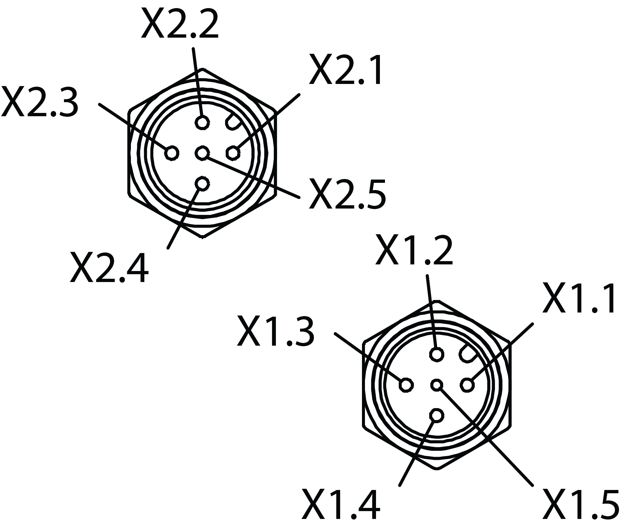 | X 1.1 | UB | Operating voltage, 24 V DC | BN |
| X 1.2 | OA | Safety output, channel 1 | WH | |
| X 1.3 | 0 V | Operating voltage, 0 V | BU | |
| X 1.4 | OB | Safety output, channel 2 | BK | |
| X 1.5 | - | n.c. | GY | |
| X 2.1 | - | n.c. | BN | |
| X 2.2 | - | n.c. | WH | |
| X 2.3 | 0VUCM | Solenoid, 0 V | BU | |
| X 2.4 | UCM | Operating voltage of guard locking solenoid, 24 V DC | BK | |
| X 2.5 | - | n.c. | GY |
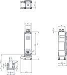
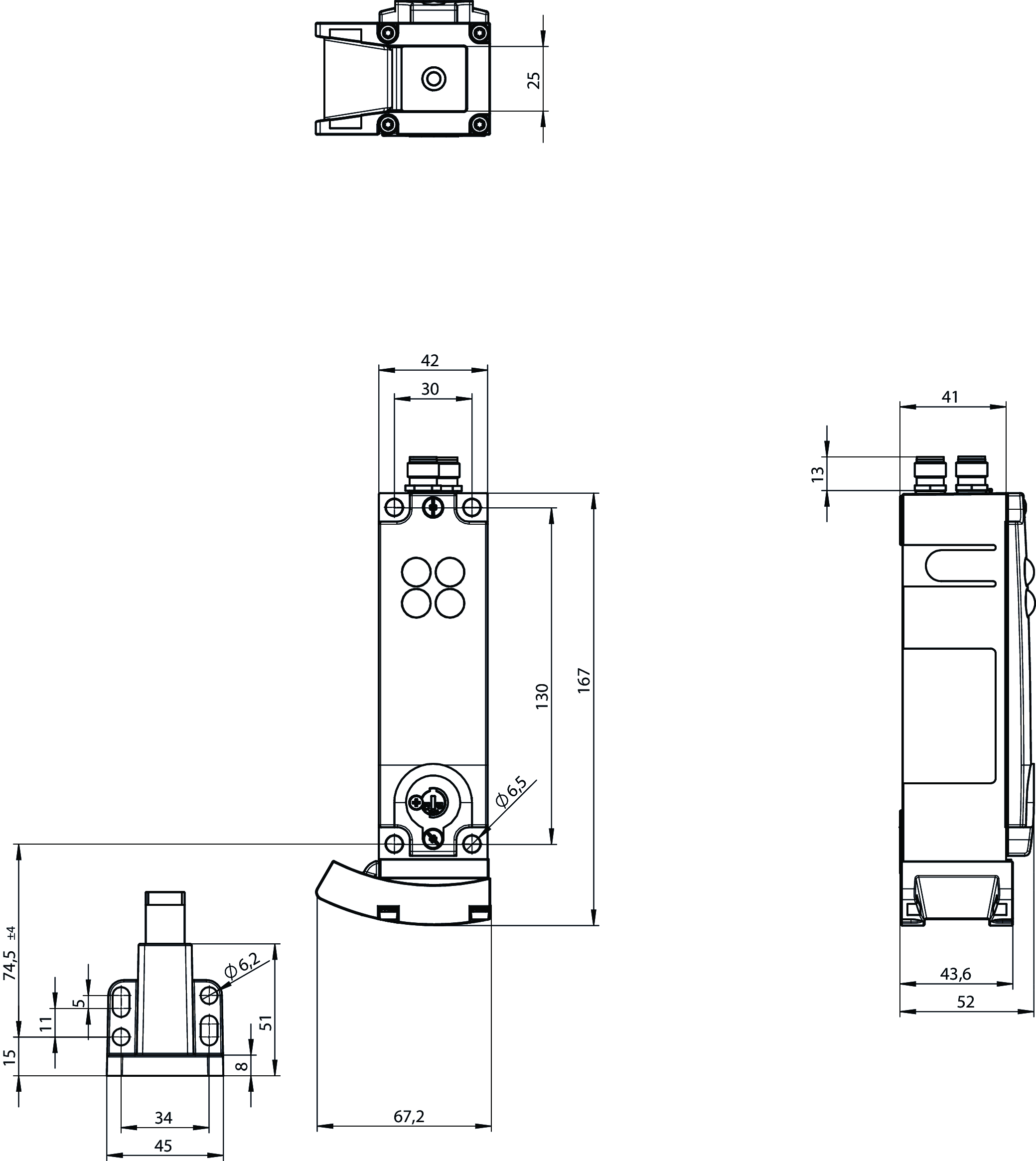
Dimensional drawings
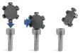
Connection examples
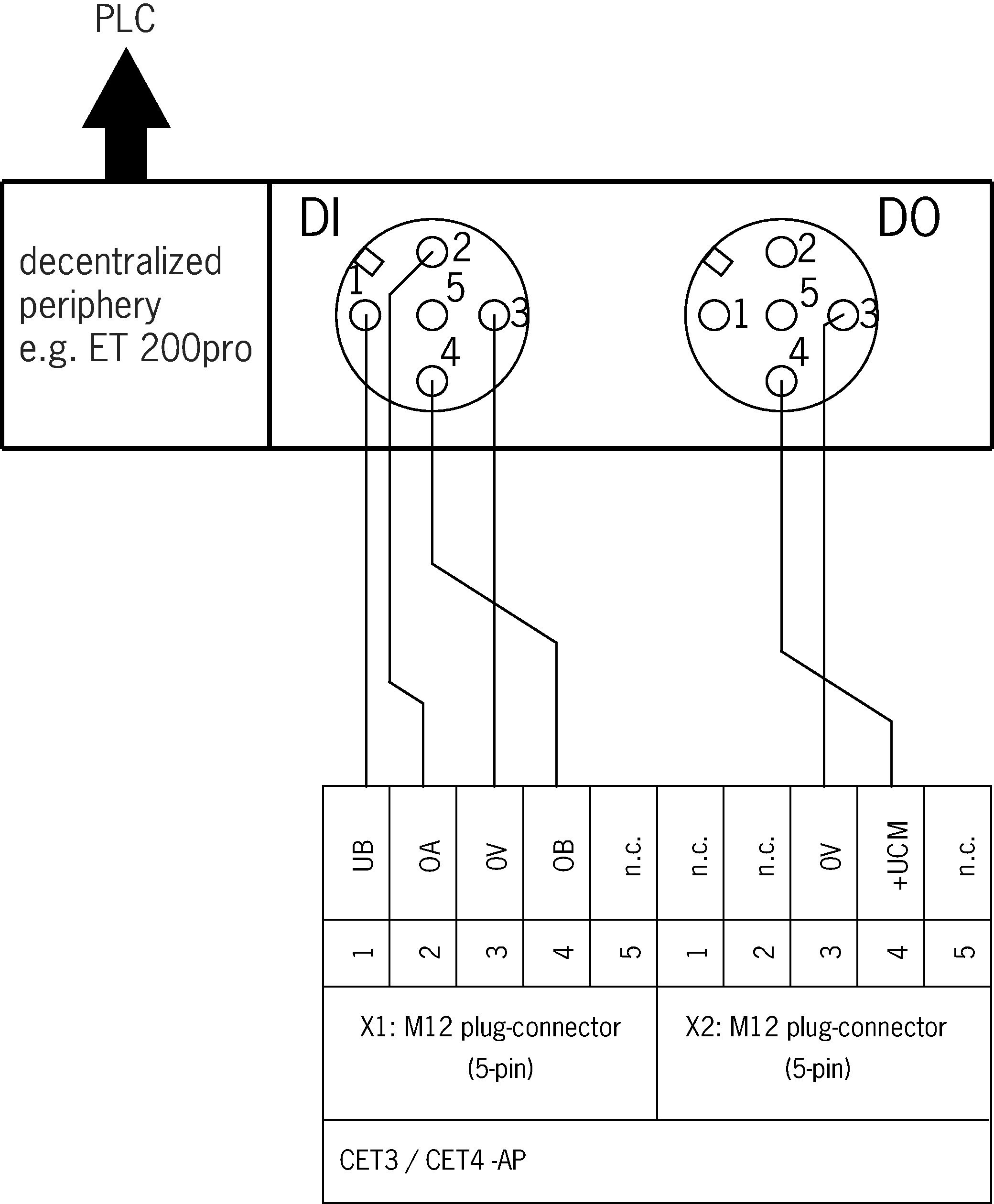
Connection examples
Technical data
Approvals


Workspace
| Repeat accuracy R | |
| according to EN 60947-5-2 | 10 % |
Electrical connection values
| Fuse | |
| external (solenoid operating voltage UCM) | 0.5 ... 8 A |
| external (operating voltage UB) | 0.25 ... 8 A |
| Power consumption | |
| Solenoid | 11 W |
| Connecting cable | 30V DC, 2A (for UL requirement UL category code (CYJV/CYJV7)) |
| Operating voltage DC | |
| LED | 24 V DC -15% V DC ... +10% V DC |
| UB | 24 V DC -15% ... +15% reverse polarity protected, regulated, residual ripple<5%, PELV |
| EMC protection requirements | Acc. to EN IEC 60947-5-3 |
| Utilization category | |
| DC-13 | 24 V 200 mA (Caution: outputs must be protected with a free-wheeling diode in case of inductive loads) |
| Solenoid operating voltage DC | |
| UCM | 24 V DC -15% ... +10% reverse polarity protected, regulated, residual ripple<5%, PELV |
| Solenoid duty cycle | 100 % |
| Risk time according to EN 60947-5-3 | max. 400 ms |
| Switching load | |
| according to UL | 24V DC, Class 2 (For alternatives, see operating instructions) |
| Safety class | III |
| Current consumption | |
| ICM | 450 mA |
| IB | 80 mA |
| Test pulse duration | max. 0.3 ms (Applies to a load with C<= 30 nF and R<= 20 kohm) |
| Degree of contamination (external, according to EN 60947-1) | 3 |
Mechanical values and environment
| Approach speed | max. 20 m/min |
| Connection type | 2 plug connector M12, 5-pin |
| Ready delay | 1 s |
| Installation orientation | any |
| Switching frequency | max. 0.5 Hz |
| Degree of freedom X | ±5 mm |
| Degree of freedom Y | ±5 mm |
| Degree of freedom Z | ±4 mm |
| Mechanical life | 2 x 10⁶ |
| Shock and vibration resistance | Acc. to EN IEC 60947-5-3 |
| Degree of protection | IP67 (When inserted and secured) |
| Ambient temperature | |
| with UB = 24 V DC | -20 ... +55 °C |
| Material | |
| Ramp | Stainless steel |
| Safety switch housing | Die-cast aluminum |
| Locking force Fmax | 6500 N |
| Locking force FZh | 5000 N |
| Guard locking principle | Closed-circuit current principle |
Characteristic values according to EN ISO 13849-1 and EN IEC 62061
| PL | Maximum SIL | PFHD | Category | Mission time | |
|---|---|---|---|---|---|
| Monitoring of guard locking | PL e | - | 3.1x10⁻⁹ | 4 | 20 y |
| PL | Maximum SIL | Category | Mission time | |
|---|---|---|---|---|
| Control of guard locking | Depending on external control of guard locking | 20 y | ||
Miscellaneous
| Notices for UL approval | Operation only with UL Class 2 power supply or equivalent measures; see operating instructions |
Accessories


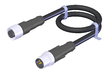
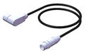
C-M12F05-05X034PU01,5-M12M05-159356
- M12 female plug to M12 plug connector, 5-pin
- Straight female plug and plug connector
- Connecting cable according to AIDA standard
- PUR cable, sheath color gray
- Cable length 1.5 m

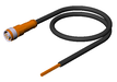
C-M12F05-05X034PU01,5-M12M05-159363
- M12 female plug to M12 plug connector, 5-pin
- Straight female plug and plug connector
- Connecting cable according to AIDA standard
- PUR cable, sheath color yellow
- Cable length 1.5 m
C-M12F05-05X034PV10,0-M12M05-100181
- M12 female plug to M12 plug connector, 5-pin
- Straight female plug and plug connector
- PVC cable
- Cable length 10 m
C-M12F05-05X034PU10,0-M12M05-119947
- M12 female plug to M12 plug connector, 5-pin
- Straight female plug and plug connector
- PUR cable
- Cable length 10 m
C-M12F05-05X034PU10,0-M12M05-159360
- M12 female plug to M12 plug connector, 5-pin
- Straight female plug and plug connector
- Connecting cable according to AIDA standard
- PUR cable, sheath color gray
- Cable length 10 m
C-M12F05-05X034PU10,0-M12M05-159920
- M12 female plug to M12 plug connector, 5-pin
- Straight female plug and plug connector
- Connecting cable according to AIDA standard
- PUR cable, sheath color yellow
- Cable length 10 m
C-M12F05-05X034PU15,0-M12M05-159361
- M12 female plug to M12 plug connector, 5-pin
- Straight female plug and plug connector
- Connecting cable according to AIDA standard
- PUR cable, sheath color gray
- Cable length 15 m
C-M12F05-05X034PU15,0-M12M05-159921
- M12 female plug to M12 plug connector, 5-pin
- Straight female plug and plug connector
- Connecting cable according to AIDA standard
- PUR cable, sheath color yellow
- Cable length 15 m
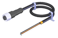
C-M12F05-05X034PU01,0-M12M05-159355
- M12 female plug to M12 plug connector, 5-pin
- Straight female plug and plug connector
- Connecting cable according to AIDA standard
- PUR cable, sheath color gray
- Cable length 1 m
C-M12F05-05X034PU01,0-M12M05-159362
- M12 female plug to M12 plug connector, 5-pin
- Straight female plug and plug connector
- Connecting cable according to AIDA standard
- PUR cable, sheath color yellow
- Cable length 1 m
C-M12F05-05X034PV20,0-M12M05-100182
- M12 female plug to M12 plug connector, 5-pin
- Straight female plug and plug connector
- PVC cable
- Cable length 20 m
C-M12F05-05X034PU20,0-M12M05-119971
- M12 female plug to M12 plug connector, 5-pin
- Straight female plug and plug connector
- PUR cable
- Cable length 20 m
C-M12F05-05X034PU03,0-M12M05-159357
- M12 female plug to M12 plug connector, 5-pin
- Straight female plug and plug connector
- Connecting cable according to AIDA standard
- PUR cable, sheath color gray
- Cable length 3 m
C-M12F05-05X034PU03,0-M12M05-159364
- M12 female plug to M12 plug connector, 5-pin
- Straight female plug and plug connector
- Connecting cable according to AIDA standard
- PUR cable, sheath color yellow
- Cable length 3 m
C-M12F05-05X034PV05,0-M12M05-100180
- M12 female plug to M12 plug connector, 5-pin
- Straight female plug and plug connector
- PVC cable
- Cable length 5 m
C-M12F05-05X034PU05,0-M12M05-119932
- M12 female plug to M12 plug connector, 5-pin
- Straight female plug and plug connector
- PUR cable
- Cable length 5 m
C-M12F05-05X034PU05,0-M12M05-159358
- M12 female plug to M12 plug connector, 5-pin
- Straight female plug and plug connector
- Connecting cable according to AIDA standard
- PUR cable, sheath color gray
- Cable length 5 m
C-M12F05-05X034PU05,0-M12M05-159365
- M12 female plug to M12 plug connector, 5-pin
- Straight female plug and plug connector
- Connecting cable according to AIDA standard
- PUR cable, sheath color yellow
- Cable length 5 m
C-M12F05-05X034PU08,0-M12M05-159359
- M12 female plug to M12 plug connector, 5-pin
- Straight female plug and plug connector
- Connecting cable according to AIDA standard
- PUR cable, sheath color gray
- Cable length 8 m
C-M12F05-05X034PU08,0-M12M05-159919
- M12 female plug to M12 plug connector, 5-pin
- Straight female plug and plug connector
- Connecting cable according to AIDA standard
- PUR cable, sheath color yellow
- Cable length 8 m
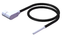
C-M12F05-05X025PU10,0-M12M05-115565
- M12 female plug, 5-pin (angled) to M12 plug connector (straight)
- plug connectors at both ends
- PUR cable
- Cable length 10 m
- with cable exit A (right)
C-M12F05-05X025PU10,0-M12M05-115566
- M12 female plug, 5-pin (angled) to M12 plug connector (straight)
- plug connectors at both ends
- PUR cable
- Cable length 10 m
- with cable exit C (left)


AM-C-SW4-V3-161344
- Plastic inserts for hexagon socket screws a/f 4
- Efficient protection against tampering for safety switch mounting
- The packaging includes inserts for 18 screws
AM-C-SW5-V3-161348
- Plastic inserts for hexagon socket screws a/f 5
- Efficient protection against tampering for safety switch mounting
- The packaging includes inserts for 18 screws

Downloads
Complete package
Download all important documents with a single click.
Content:
- The operating instructions and any additions to the operating instructions or brief instructions
- Any data sheets to supplement the operating instructions
- The declaration of conformity
Single Documents


Other Documents


CAD data

Ordering data
| Ordernumber | 111346 |
| Item designation | CET3-AP-CRA-AH-50X-SI-111346 |
| Gross weight | 1,265kg |
| Global Trade Item Number (GTIN) | 4047048006751 |
| Customs tariff number | 85365019000 |
| ECLASS | 27-27-24-05 Safety-related transponder switch with guardlocking |

Technical support
Do you have technical questions about our products, their possible use or applications? Our experts will be happy to help.
EUCHNER (UK) Ltd.
+44 114 2560123
sales@euchner.co.uk
EUCHNER USA Inc.
+1 315 701-0315
info@euchner-usa.com