HomeProductsTransponder-coded safety switches with guard lockingCTPCTP-ASCTP-L1-AS1B-M-HA-AZ-SJ-126645
CTP-L1-AS1B-M-HA-AZ-SJ-126645 (Order no. 126645)
Choose content
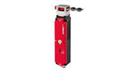
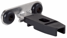
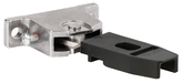
Safety switch CTP-L1-AS – with AS-i connection, plug connector M12 (closed-circuit current principle)
- Safety switch with guard locking and integrated evaluation electronics
- Locking force up to 3,900 N
- Category 4 / PL e according to EN ISO 13849-1
- Multicode
- Approach directions A, B and C (delivery state)
Description
Approach direction
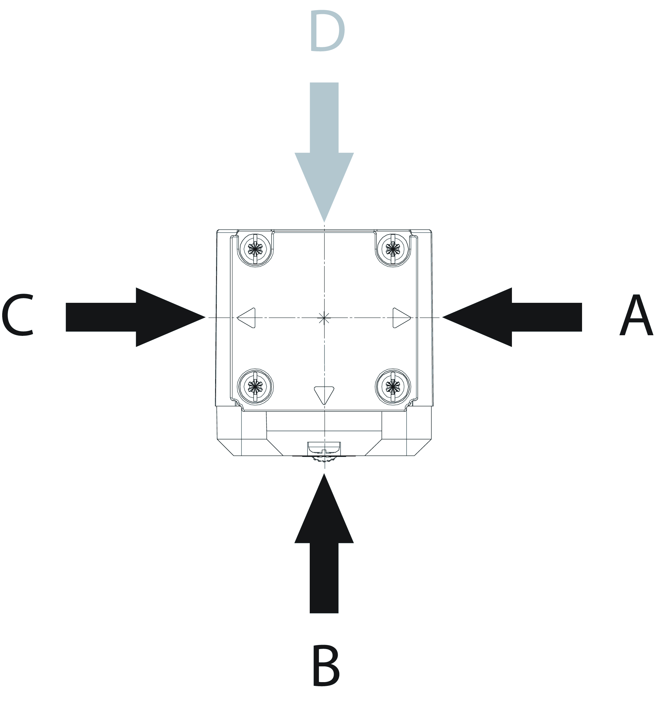
Horizontal
Can be adjusted in 90° steps
Guard locking type
CTP‑L1 | Guard locking actuated by spring force and power-ON released (closed-circuit current principle). |
Control of the guard locking solenoid
The guard locking solenoid can be controlled via AS-Interface bus bit D0 or via the auxiliary power.
AS-Interface inputs
D0, D1 | Door monitoring |
D2, D3 | Guard lock monitoring |
Evaluation is performed via a safety monitor.
AS-Interface outputs
D0 | Guard locking |
LED function display
- The ASI LED indicates the state of the ASi bus.
- The STATE LED indicates the state of the switch.
- The LOCK/DIA LED indicates if the door is locked and whether a fault has been detected in the switch.
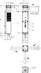
Dimensional drawings
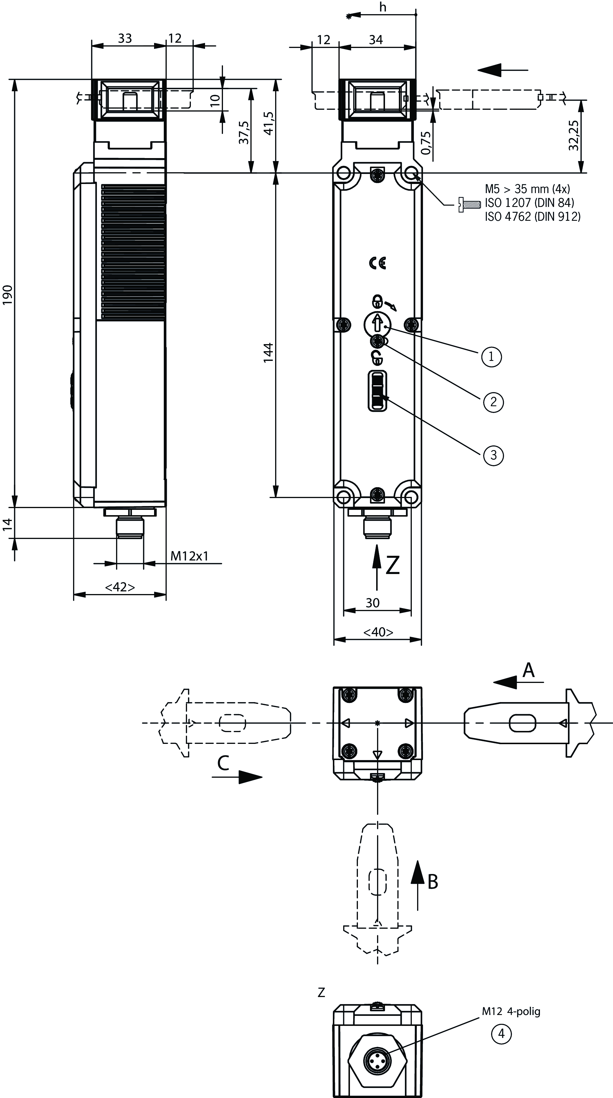
| 1 | Auxiliary release basic position *) |
| 2 | Locking screw |
| 3 | LEDs |
| 4 | M12, 4-pin |
| Plug connector not aligned |
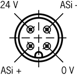
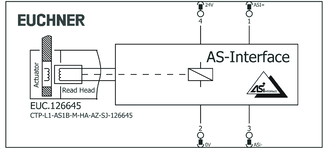
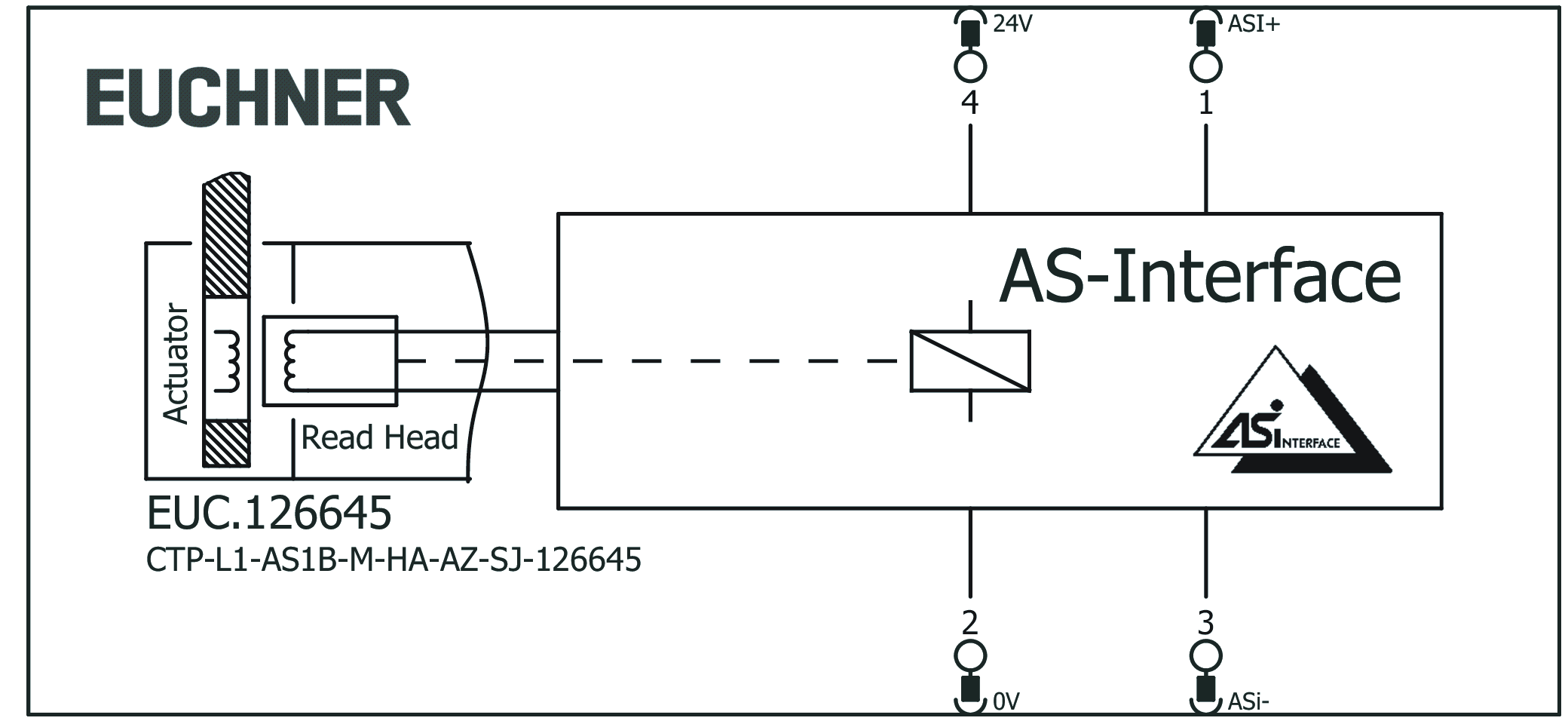
Connection examples

| View of plug side |
Connection examples
Technical data
Approvals


Workspace
| Repeat accuracy R | |
| according to EN 60947-5-2 | 10 % |
Electrical connection values
| ASI operating current | max. 50 mA |
| AS-Interface auxiliary voltage | 24 V -15 ... 10 % |
| Auxiliary current AS-Interface | 400 mA |
| AS-Interface protocol | ASi-3 |
| ASI data out | D0 = Control of guard locking |
| ASI data in | D0, D1 = door position, D2, D3 = guard locking |
| AS-Interface slave type | ID-Code: B, EA-Code: 7 |
| ASI voltage | 26.5 ... 30 ... 31.6 V |
| Safety class | III |
Mechanical values and environment
| Approach speed | max. 20 m/min |
| Connection type | 1 plug connector M12, 4-pin |
| Extraction force | 20 N |
| Ready delay | max. 1 s |
| Actuating force | 10 N |
| Installation orientation | any |
| Switching frequency | max. 0.5 Hz |
| Mechanical life | 1 x 10⁶ |
| Overtravel | 5 mm |
| Retention force | 20 N |
| Shock and vibration resistance | Acc. to EN IEC 60947-5-3 |
| Degree of protection | IP67/IP69/IP69K (When inserted and secured) |
| Ambient temperature | -20 ... +55 °C |
| Material | |
| Safety switch housing | Reinforced thermoplastic |
| Switch head cover | Die-cast zinc |
| Locking force Fmax | 3900 N |
| Locking force FZh | 3000 N (Fzh = Fmax/1.3, depending on the actuator used) |
| Guard locking principle | Closed-circuit current principle |
Characteristic values according to EN ISO 13849-1 and EN IEC 62061
| PL | Maximum SIL | PFHD | Category | Mission time | |
|---|---|---|---|---|---|
| Monitoring of the guard position | PL e | - | 4.1x10⁻⁹ | 4 | 20 y |
| PL | Maximum SIL | Category | Mission time | |
|---|---|---|---|---|
| Control of guard locking | Depending on external control of guard locking | 20 y | ||
Miscellaneous
| Notices for UL approval | Operation only with UL Class 2 power supply or equivalent measures; see operating instructions |
Accessories
Actuator

Hinged actuator for safety switch CTP/CTA


122671
A-C-H-RL-LS-122671
A-C-H-RL-LS-122671
- Hinged actuator for doors hinged on the left
- Two safety screws included
122672
A-C-H-RR-LS-122672
A-C-H-RR-LS-122672
- Hinged actuator for doors hinged on the right
- Two safety screws included
122675
A-C-H-RO-LS-122675
A-C-H-RO-LS-122675
- Hinged actuator for top-hinged doors
- Two safety screws included
122676
A-C-H-RU-LS-122676
A-C-H-RU-LS-122676
- Hinged actuator for bottom-hinged doors
- Two safety screws included

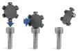
Function expansion


Lock for auxiliary release for safety switch CTP/CTA/TP/STP


084177
AE-K-A1-DULK1-84177
AE-K-A1-DULK1-84177
- Lock unique locking
- Key removable in “unlocked” and “locked” positions
086236
AE-K-A1-IULK1-86236
AE-K-A1-IULK1-86236
- Identical locking
- Key removable in “unlocked” and “locked” positions
109212
AE-K-A1-IUK2-109212
AE-K-A1-IUK2-109212
- Identical locking
- Key can be removed only in “unlocked” position
121917
AE-K-A1-ILK1-121917
AE-K-A1-ILK1-121917
- Identical locking
- Key removable in “locked” position


Wire front release (bowden)

096230
AE-B-A1-02,0-096230
AE-B-A1-02,0-096230
- Can be used as escape release or emergency release
- no automatic return
- Sheath length 2 m (rope length 6 m)
097747
AE-B-A1-02,0-F-097747
AE-B-A1-02,0-F-097747
- Can be used as escape release or emergency release
- automatic return
- Sheath length 2 m (rope length 6 m)
098313
AE-B-A1-03,0-098313
AE-B-A1-03,0-098313
- Can be used as escape release or emergency release
- no automatic return
- Sheath length 3 m (rope length 6 m)
098314
AE-B-A1-04,0-098314
AE-B-A1-04,0-098314
- Can be used as escape release or emergency release
- no automatic return
- Sheath length 4 m (rope length 6 m)
111233
AE-B-A1-03,0-F-111233
AE-B-A1-03,0-F-111233
- Can be used as escape release or emergency release
- automatic return
- Sheath length 3 m (rope length 6 m)
125582
AE-B-A1-06,0-125582
AE-B-A1-06,0-125582
- Can be used as escape release or emergency release
- no automatic return
- Rope length 6 m (without sheath)
124770
AE-B-A1-06,0-F-124770
AE-B-A1-06,0-F-124770
- Can be used as escape release or emergency release
- automatic return
- Rope length 6 m (without sheath)
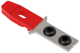
Metal bolt


Bolt for safety switch CTP, CTA

123653
RIEGEL CTP-AC-123653
RIEGEL CTP-AC-123653
- Steel bolt
- For doors hinged on the right and left
- Can be locked in open position with padlocks
- Actuator included
137354
RIEGEL CTP-AC-C2308-137354
RIEGEL CTP-AC-C2308-137354
- Steel bolt
- For doors hinged on the right and left
- Can be locked in open position with padlocks
- Actuator included
- Bolt without door stop, suitable for swing doors
Mounting accessories
Efficient protection against tampering for safety switch mounting
161344
AM-C-SW4-V3-161344
AM-C-SW4-V3-161344
- Plastic inserts for hexagon socket screws a/f 4
- Efficient protection against tampering for safety switch mounting
- The packaging includes inserts for 18 screws
161348
AM-C-SW5-V3-161348
AM-C-SW5-V3-161348
- Plastic inserts for hexagon socket screws a/f 5
- Efficient protection against tampering for safety switch mounting
- The packaging includes inserts for 18 screws
Downloads
Complete package
Download all important documents with a single click.
Content:
- The operating instructions and any additions to the operating instructions or brief instructions
- Any data sheets to supplement the operating instructions
- The declaration of conformity
Download Complete Package (ZIP, 3,7 MB)
Single Documents
Declarations of conformity
EU-Konformitätserklärung

Doc. no.
Version
Language
Size
EU-Konformitätserklärung
Doc. no.
EDC2123042
Version
Language
Size
0,2 MB
UKCA-Konformitätserklärung

Doc. no.
Version
Language
Size
UKCA-Konformitätserklärung
Doc. no.
EDC20001501
Version
Language
Size
0,1 MB
Instructions
Operating Instructions Transponder-Coded Safety Switch with Guard Locking CTP-L.-AS Unicode/Multicode


Doc. no.
Version
Language
Size
Operating Instructions Transponder-Coded Safety Switch with Guard Locking CTP-L.-AS Unicode/Multicode
Doc. no.
2124662
Version
05/23
Language
Size
3,2 MB
Betriebsanleitung Transpondercodierter Sicherheitsschalter mit Zuhaltung CTP-L.-AS Uni-/Multicode
Doc. no.
2124662
Version
05/23
Language
Size
3,2 MB

Other Documents
Approvals and certificates

Asi Interface

Doc. no.
Version
Language
Size
Asi Interface
Doc. no.
Version
Language
Size
0,4 MB
DGUV

Doc. no.
Version
Language
Size
DGUV
Doc. no.
Version
Language
Size
2,4 MB
c UL us

Doc. no.
Version
Language
Size
c UL us
Doc. no.
Version
Language
Size
0,3 MB
UQS document
Bescheinigung

Doc. no.
Version
Language
Size
Bescheinigung
Doc. no.
ECO2125542
Version
Language
Size
0,2 MB
CAD data

Ordering data
| Ordernumber | 126645 |
| Item designation | CTP-L1-AS1B-M-HA-AZ-SJ-126645 |
| Gross weight | 0,6kg |
| Customs tariff number | 85365019000 |
| ECLASS | 27-27-24-05 Safety-related transponder switch with guardlocking |
