HomeProductsTransponder-coded safety switches without guard lockingCTP-I-AP safety switch without guard lockingCTP-I-AP-U-HA-ZZE-SBB-159614
CTP-I-AP-U-HA-ZZE-SBB-159614 (Order no. 159614)
Choose content
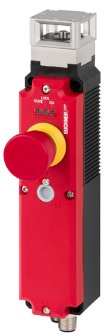
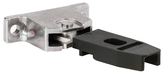
Transponder-coded safety switch CTP-I-AP, 2 x M12, emergency stop (extended)
- Safety switch without guard locking, with integrated evaluation electronics
- Direct connection to decentralized peripheral systems (e.g. ET200pro)
- Short circuit monitoring
- 2 safety outputs (semiconductor outputs)
- Up to category 4 / PL e according to EN ISO 13849-1
- With 2 plug connectors M12
- Unicode
- Emergency stop
- Approach directions A, B and C (delivery state)
Description
Approach direction
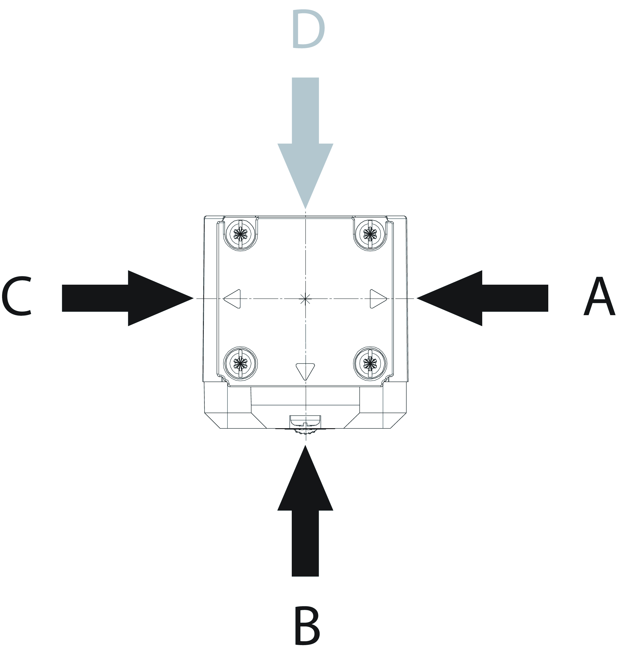
Horizontal
Can be adjusted in 90° steps
Unicode evaluation
Each actuator is highly coded (unicode). The switch detects only taught-in actuators. Additional actuators can be taught-in. Only the last actuator taught-in is detected.
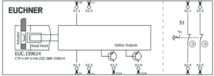
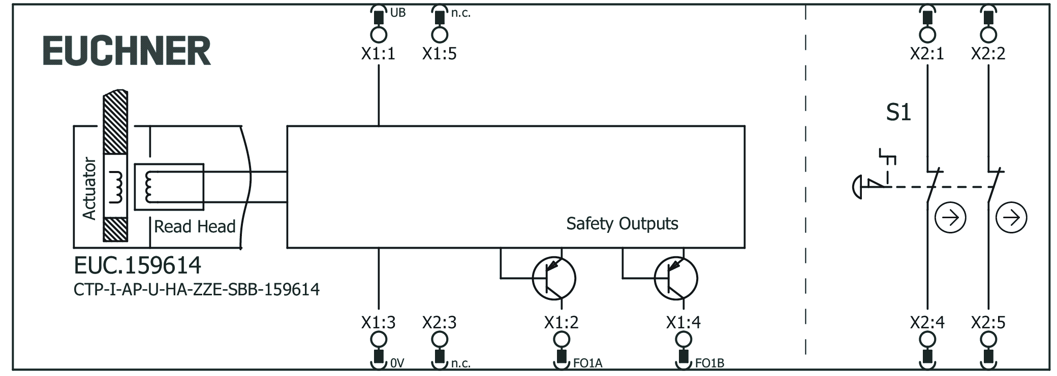
Connector assignment
| Plug connector (view of connection side) | Pin | Designation | Function | Connecting cable conductor coloring |
|---|---|---|---|---|
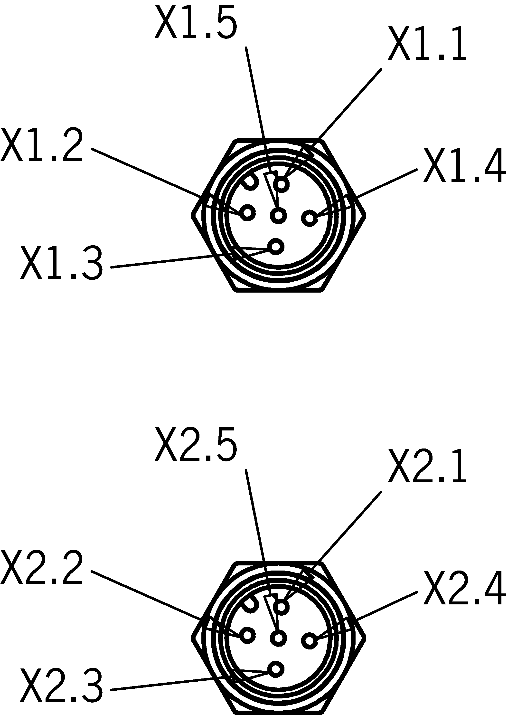 | X 1.1 | UB | Electronics operating voltage 24 V DC | BN |
| X 1.2 | FO1A | Safety output, channel 1 | WH | |
| X 1.3 | 0 V UB | Electronics operating voltage 0 V | BU | |
| X 1.4 | FO1B | Safety output, channel 2 | BK | |
| X 1.5 | - | n.c. | GY | |
| X 2.1 | S1.A1 | EMERGENCY STOP (channel A) | BN | |
| X 2.2 | S1.B1 | EMERGENCY STOP (channel B) | WH | |
| X 2.3 | - | n.c. | BU | |
| X 2.4 | S1.A2 | EMERGENCY STOP (channel A) | BK | |
| X 2.5 | S1.B2 | EMERGENCY STOP (channel B) | GY |
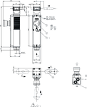
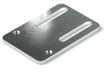
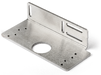
Dimensional drawings
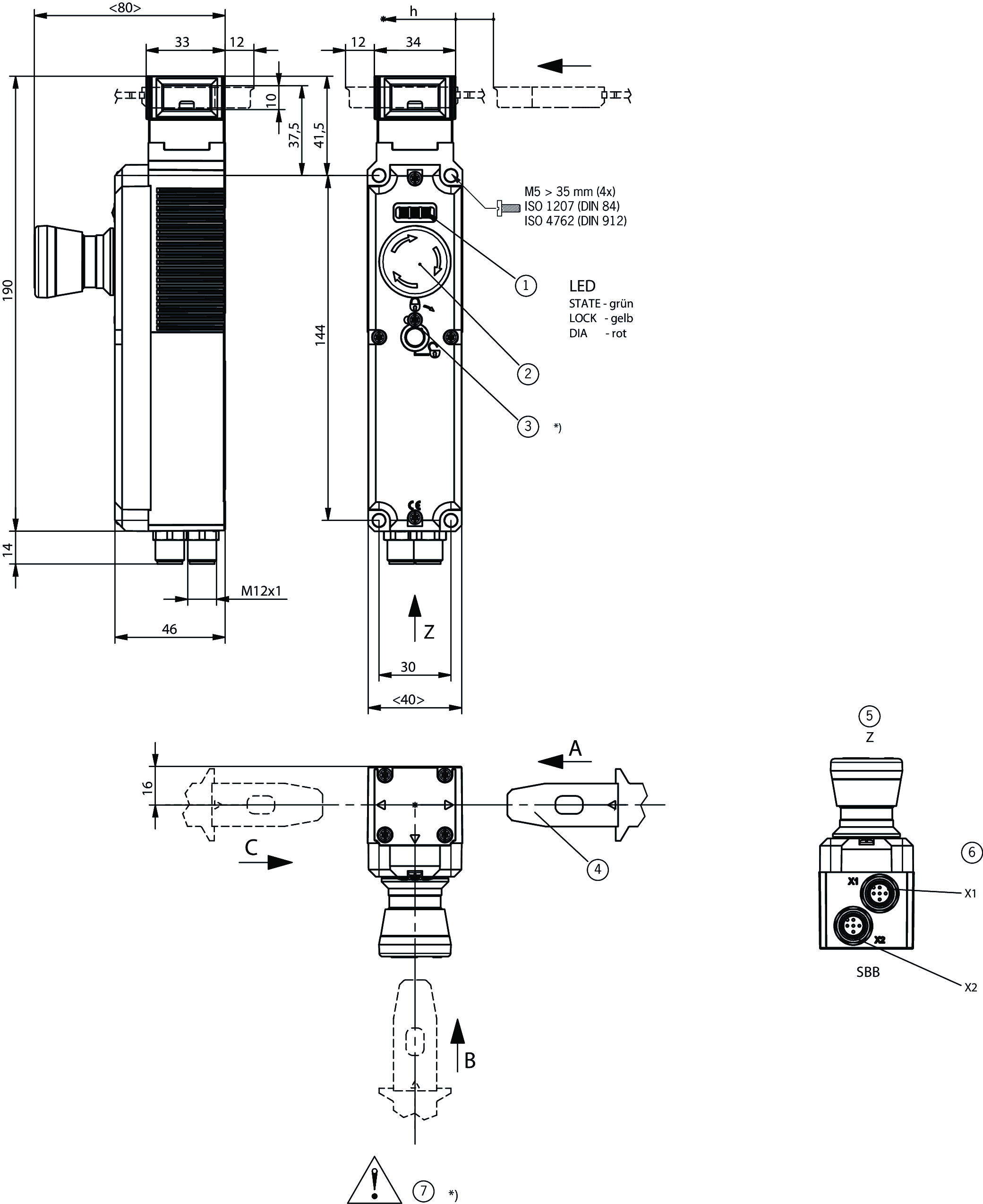
| 1 | LEDs: STATE green; LOCK yellow; DIA red |
| 2 | EMERGENCY STOP |
| 3 | Auxiliary release has no basic-position function *) |
| 4 | Order actuator separately |
| 5 | View Z |
| 6 | Plug connector aligned X1 M12, 5-pin; plug connector aligned X2 M12, 5-pin |
| 7 | Safety switch without auxiliary release *) Auxiliary release without function |
Connection examples
Technical data
Approvals


Workspace
| Repeat accuracy R | |
| according to EN 60947-5-2 | 10 % |
Operating and display elements
| Item | Color | Extras | Note slide-in label | Version | Switching element | Slide-in label | Number | Designation1 | LED |
|---|---|---|---|---|---|---|---|---|---|
| 1 | Emergency stop | 2 PD |
Electrical connection values
| Fuse | |
| external (operating voltage UB) | 0.25 ... 8 A |
| Power consumption | 1 W |
| Rated insulation voltage Ui | 50 V |
| Rated impulse voltage Uimp | 0.5 kV |
| Operating voltage DC | |
| UUB | 24 V DC -15% ... +15% reverse polarity protected, regulated, residual ripple<5%, PELV |
| EMC protection requirements | Acc. to EN IEC 60947-5-3 |
| Utilization category | |
| DC-13 | 24 V 150 mA (Caution: outputs must be protected with a free-wheeling diode in case of inductive loads) |
| Switching load | |
| according to UL | 24V DC, Class 2 (alternatively, see operating instructions) |
| Safety class | III |
| Current consumption | |
| IUB | 40 mA |
| Test pulse duration | max. 0.3 ms (Applies to a load with C<= 30 nF and R<= 20 kohm) |
| Test pulse interval | min. 100 ms |
| Degree of contamination (external, according to EN 60947-1) | 3 |
| Emergency stop | |
| Breaking capacity | max. 0.25 W |
| Switching voltage | 5 ... 24 V |
| Switching current | 1 ... 100 mA |
| Safety outputs FO1A / FO1B | |
| Output type | 2 semiconductor outputs, p-switching, short circuit-proof |
| Output voltage | |
| HIGH U(FO1A) / U(FO1B) | UB-1.5 ... UB V DC |
| LOW U(FO1A) / U(FO1B) | 0 ... 1 V DC |
| Discrepancy time | |
| both safety outputs | max. 10 ms Acc. to EN IEC 60947-5-3 |
| Turn-on time | max. 400 ms |
| Off-state current Ir | max. 0.25 mA |
| Switching current | |
| per safety output FO1A / FO1B | 1 ... 150 mA |
Mechanical values and environment
| Approach speed | max. 20 m/min |
| Connection type | 2 plug connector M12, 5-pin |
| Extraction force | 20 N |
| Ready delay | max. 1 s |
| Actuating force | 10 N |
| Installation orientation | any |
| Switching frequency | max. 0.5 Hz |
| Mechanical life | 1 x 10⁶ |
| Overtravel | 5 mm |
| Shock and vibration resistance | Acc. to EN IEC 60947-5-3 |
| Degree of protection | IP65 (When inserted and secured) |
| Ambient temperature | |
| with UB = 24 V DC | -20 ... +55 °C |
| Material | |
| Safety switch housing | Reinforced thermoplastic |
| Switch head cover | Die-cast zinc |
Characteristic values according to EN ISO 13849-1 and EN IEC 62061
| Mission time | 20 y |
| Category | 4 |
| Performance Level | PL e |
| PFHD | 4.1 x 10 -9 |
Characteristic values according to EN ISO 13849-1 and EN IEC 62061
| PL | Maximum SIL | PFHD | Category | Mission time | |
|---|---|---|---|---|---|
| Monitoring of the guard position | PL e | - | 4.1x10⁻⁹ | 4 | 20 y |
| B10D | Mission time | |
|---|---|---|
| Emergency stop | 0.13x10⁶ | 20 y |
Miscellaneous
| Notices for UL approval | Operation only with UL Class 2 power supply or equivalent measures; see operating instructions |
| Detent mechanism | Snap-in bolt |
Accessories
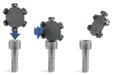
Actuator
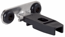

Hinged actuator for safety switch CTP/CTA


122671
A-C-H-RL-LS-122671
A-C-H-RL-LS-122671
- Hinged actuator for doors hinged on the left
- Two safety screws included
122672
A-C-H-RR-LS-122672
A-C-H-RR-LS-122672
- Hinged actuator for doors hinged on the right
- Two safety screws included
122675
A-C-H-RO-LS-122675
A-C-H-RO-LS-122675
- Hinged actuator for top-hinged doors
- Two safety screws included
122676
A-C-H-RU-LS-122676
A-C-H-RU-LS-122676
- Hinged actuator for bottom-hinged doors
- Two safety screws included
Connection material
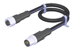
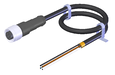
Connecting cable with 2 plug connectors M12, 5-pin, 1.5 m, AIDA standard


159356
C-M12F05-05X034PU01,5-M12M05-159356
C-M12F05-05X034PU01,5-M12M05-159356
- M12 female plug to M12 plug connector, 5-pin
- Straight female plug and plug connector
- Connecting cable according to AIDA standard
- PUR cable, sheath color gray
- Cable length 1.5 m
159363
C-M12F05-05X034PU01,5-M12M05-159363
C-M12F05-05X034PU01,5-M12M05-159363
- M12 female plug to M12 plug connector, 5-pin
- Straight female plug and plug connector
- Connecting cable according to AIDA standard
- PUR cable, sheath color yellow
- Cable length 1.5 m
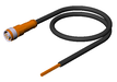
Connecting cable with 2 plug connectors M12, 5-pin, 10 m
100181
C-M12F05-05X034PV10,0-M12M05-100181
C-M12F05-05X034PV10,0-M12M05-100181
- M12 female plug to M12 plug connector, 5-pin
- Straight female plug and plug connector
- PVC cable
- Cable length 10 m
119947
C-M12F05-05X034PU10,0-M12M05-119947
C-M12F05-05X034PU10,0-M12M05-119947
- M12 female plug to M12 plug connector, 5-pin
- Straight female plug and plug connector
- PUR cable
- Cable length 10 m
Connecting cable with 2 plug connectors M12, 5-pin, 10 m, AIDA standard
159360
C-M12F05-05X034PU10,0-M12M05-159360
C-M12F05-05X034PU10,0-M12M05-159360
- M12 female plug to M12 plug connector, 5-pin
- Straight female plug and plug connector
- Connecting cable according to AIDA standard
- PUR cable, sheath color gray
- Cable length 10 m
159920
C-M12F05-05X034PU10,0-M12M05-159920
C-M12F05-05X034PU10,0-M12M05-159920
- M12 female plug to M12 plug connector, 5-pin
- Straight female plug and plug connector
- Connecting cable according to AIDA standard
- PUR cable, sheath color yellow
- Cable length 10 m
Connecting cable with 2 plug connectors M12, 5-pin, 15 m, AIDA standard
159361
C-M12F05-05X034PU15,0-M12M05-159361
C-M12F05-05X034PU15,0-M12M05-159361
- M12 female plug to M12 plug connector, 5-pin
- Straight female plug and plug connector
- Connecting cable according to AIDA standard
- PUR cable, sheath color gray
- Cable length 15 m
159921
C-M12F05-05X034PU15,0-M12M05-159921
C-M12F05-05X034PU15,0-M12M05-159921
- M12 female plug to M12 plug connector, 5-pin
- Straight female plug and plug connector
- Connecting cable according to AIDA standard
- PUR cable, sheath color yellow
- Cable length 15 m
Connecting cable with 2 plug connectors M12, 5-pin, 1 m, AIDA standard
159355
C-M12F05-05X034PU01,0-M12M05-159355
C-M12F05-05X034PU01,0-M12M05-159355
- M12 female plug to M12 plug connector, 5-pin
- Straight female plug and plug connector
- Connecting cable according to AIDA standard
- PUR cable, sheath color gray
- Cable length 1 m
159362
C-M12F05-05X034PU01,0-M12M05-159362
C-M12F05-05X034PU01,0-M12M05-159362
- M12 female plug to M12 plug connector, 5-pin
- Straight female plug and plug connector
- Connecting cable according to AIDA standard
- PUR cable, sheath color yellow
- Cable length 1 m
Connecting cable with 2 plug connectors M12, 5-pin, 20 m
100182
C-M12F05-05X034PV20,0-M12M05-100182
C-M12F05-05X034PV20,0-M12M05-100182
- M12 female plug to M12 plug connector, 5-pin
- Straight female plug and plug connector
- PVC cable
- Cable length 20 m
119971
C-M12F05-05X034PU20,0-M12M05-119971
C-M12F05-05X034PU20,0-M12M05-119971
- M12 female plug to M12 plug connector, 5-pin
- Straight female plug and plug connector
- PUR cable
- Cable length 20 m
Connecting cable with 2 plug connectors M12, 5-pin, 3 m, AIDA standard
159357
C-M12F05-05X034PU03,0-M12M05-159357
C-M12F05-05X034PU03,0-M12M05-159357
- M12 female plug to M12 plug connector, 5-pin
- Straight female plug and plug connector
- Connecting cable according to AIDA standard
- PUR cable, sheath color gray
- Cable length 3 m
159364
C-M12F05-05X034PU03,0-M12M05-159364
C-M12F05-05X034PU03,0-M12M05-159364
- M12 female plug to M12 plug connector, 5-pin
- Straight female plug and plug connector
- Connecting cable according to AIDA standard
- PUR cable, sheath color yellow
- Cable length 3 m
Connecting cable with 2 plug connectors M12, 5-pin, 5 m
100180
C-M12F05-05X034PV05,0-M12M05-100180
C-M12F05-05X034PV05,0-M12M05-100180
- M12 female plug to M12 plug connector, 5-pin
- Straight female plug and plug connector
- PVC cable
- Cable length 5 m
119932
C-M12F05-05X034PU05,0-M12M05-119932
C-M12F05-05X034PU05,0-M12M05-119932
- M12 female plug to M12 plug connector, 5-pin
- Straight female plug and plug connector
- PUR cable
- Cable length 5 m
Connecting cable with 2 plug connectors M12, 5-pin, 5 m, AIDA standard
159358
C-M12F05-05X034PU05,0-M12M05-159358
C-M12F05-05X034PU05,0-M12M05-159358
- M12 female plug to M12 plug connector, 5-pin
- Straight female plug and plug connector
- Connecting cable according to AIDA standard
- PUR cable, sheath color gray
- Cable length 5 m
159365
C-M12F05-05X034PU05,0-M12M05-159365
C-M12F05-05X034PU05,0-M12M05-159365
- M12 female plug to M12 plug connector, 5-pin
- Straight female plug and plug connector
- Connecting cable according to AIDA standard
- PUR cable, sheath color yellow
- Cable length 5 m
Connecting cable with 2 plug connectors M12, 5-pin, 8 m, AIDA standard
159359
C-M12F05-05X034PU08,0-M12M05-159359
C-M12F05-05X034PU08,0-M12M05-159359
- M12 female plug to M12 plug connector, 5-pin
- Straight female plug and plug connector
- Connecting cable according to AIDA standard
- PUR cable, sheath color gray
- Cable length 8 m
159919
C-M12F05-05X034PU08,0-M12M05-159919
C-M12F05-05X034PU08,0-M12M05-159919
- M12 female plug to M12 plug connector, 5-pin
- Straight female plug and plug connector
- Connecting cable according to AIDA standard
- PUR cable, sheath color yellow
- Cable length 8 m
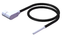
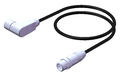
M12 extension PUR, 5-pin, plug connectors at both ends, 10 m
115565
C-M12F05-05X025PU10,0-M12M05-115565
C-M12F05-05X025PU10,0-M12M05-115565
- M12 female plug, 5-pin (angled) to M12 plug connector (straight)
- plug connectors at both ends
- PUR cable
- Cable length 10 m
- with cable exit A (right)
115566
C-M12F05-05X025PU10,0-M12M05-115566
C-M12F05-05X025PU10,0-M12M05-115566
- M12 female plug, 5-pin (angled) to M12 plug connector (straight)
- plug connectors at both ends
- PUR cable
- Cable length 10 m
- with cable exit C (left)

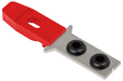
Metal bolt


Bolt for safety switch CTP, CTA

123653
RIEGEL CTP-AC-123653
RIEGEL CTP-AC-123653
- Steel bolt
- For doors hinged on the right and left
- Can be locked in open position with padlocks
- Actuator included
137354
RIEGEL CTP-AC-C2308-137354
RIEGEL CTP-AC-C2308-137354
- Steel bolt
- For doors hinged on the right and left
- Can be locked in open position with padlocks
- Actuator included
- Bolt without door stop, suitable for swing doors
Mounting accessories
Efficient protection against tampering for safety switch mounting
161344
AM-C-SW4-V3-161344
AM-C-SW4-V3-161344
- Plastic inserts for hexagon socket screws a/f 4
- Efficient protection against tampering for safety switch mounting
- The packaging includes inserts for 18 screws
161348
AM-C-SW5-V3-161348
AM-C-SW5-V3-161348
- Plastic inserts for hexagon socket screws a/f 5
- Efficient protection against tampering for safety switch mounting
- The packaging includes inserts for 18 screws

Downloads
Complete package
Download all important documents with a single click.
Content:
- The operating instructions and any additions to the operating instructions or brief instructions
- Any data sheets to supplement the operating instructions
- The declaration of conformity
Download Complete Package (ZIP, 7,1 MB)
Single Documents
Declarations of conformity
EU-Konformitätserklärung

Doc. no.
Version
Language
Size
EU-Konformitätserklärung
Doc. no.
EDC2123042
Version
Language
Size
0,2 MB
UKCA-Konformitätserklärung

Doc. no.
Version
Language
Size
UKCA-Konformitätserklärung
Doc. no.
EDC20001501
Version
Language
Size
0,1 MB
Instructions
Operating Instructions Transponder-Coded Safety Switch Without Guard Locking CTP-I-AP Unicode/Multicode


Doc. no.
Version
Language
Size
Operating Instructions Transponder-Coded Safety Switch Without Guard Locking CTP-I-AP Unicode/Multicode
Doc. no.
2137526
Version
02/21
Language
Size
2,1 MB
Mode d’emploi Interrupteur de sécurité à codage par transpondeur sans interverrouillage CTP-I-AP Uni-/multicode
Doc. no.
2137526
Version
02/21
Language
Size
2,1 MB
Manual de instrucciones Interruptor de seguridad con codificación por transponder sin bloqueo CTP-I-AP Unicode/Multicode
Doc. no.
2137526
Version
02/21
Language
Size
2,1 MB
Betriebsanleitung Transpondercodierter Sicherheitsschalter ohne Zuhaltung CTP-I-AP Uni-/Multicode
Doc. no.
2137526
Version
02/21
Language
Size
2,1 MB
Istruzioni di impiego Finecorsa di sicurezza con codifica a transponder senza meccanismo di ritenuta CTP-I-AP Unicode/Multicode
Doc. no.
2137526
Version
02/21
Language
Size
2,1 MB
操作説明書 トランスポンダー コーデッド安全スイッチ ガードロックなし CTP-I-AP ユニコード/マルチコード
Doc. no.
2137526
Version
02/21
Language
Size
2,5 MB

Other Documents
Approvals and certificates

FCC

Doc. no.
Version
Language
Size
FCC
Doc. no.
Version
Language
Size
0,1 MB
c UL us

Doc. no.
Version
Language
Size
c UL us
Doc. no.
Version
Language
Size
0,3 MB
Sales documents


UQS document
Bescheinigung

Doc. no.
Version
Language
Size
Bescheinigung
Doc. no.
ECO2123565
Version
Language
Size
0,2 MB
CAD data

Ordering data
| Ordernumber | 159614 |
| Item designation | CTP-I-AP-U-HA-ZZE-SBB-159614 |
| Gross weight | 0,56kg |
| Customs tariff number | 85365019000 |
| ECLASS | 27-27-24-05 Safety-related transponder switch with guardlocking |
