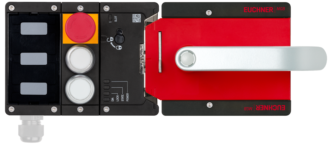
Complete set MGB2-L1...-BR (2 pushbuttons, emergency stop, closed-circuit current principle, door hinge on right)
- Guard locking with guard lock monitoring
- Emergency stop according to ISO 13850
- 2 illuminated pushbuttons
- 3 adhesive labels
- Cable entry M20 x 1.5 (order cable gland separately)
- Connection for signal light/enabling switch
- Adjustable door hinge; factory setting: right
- Unicode
Description
Guard locking type
MGB2-L1... | Guard locking by spring force. Release by applying voltage to the guard locking solenoid. (closed-circuit current principle) |
Flexible adaptation through configuration
- The evaluation module can be configured with the aid of DIP switches. Depending on the setting, the evaluation module behaves like an MGB2-BP or an MGB2-BR device.
- In addition, guard lock monitoring can be switched on or off on devices with guard locking. When guard lock monitoring is switched on, the safe outputs are switched on if the guard is safely locked. When guard lock monitoring is switched off, the safe outputs are switched on if the guard is closed and the bolt tongue is inserted into the MGB2.
- Release monitoring can be activated when guard lock monitoring is switched on. This signals whether the auxiliary release or escape release was actuated.
- Factor reset permits resetting to the factory setting.
Lens set
The color of the pushbuttons can be selected using the lens set 120344 included (5 colors).
Adhesive labels
The user can produce custom labeling using the enclosed adhesive labels. (3 pcs., blank)

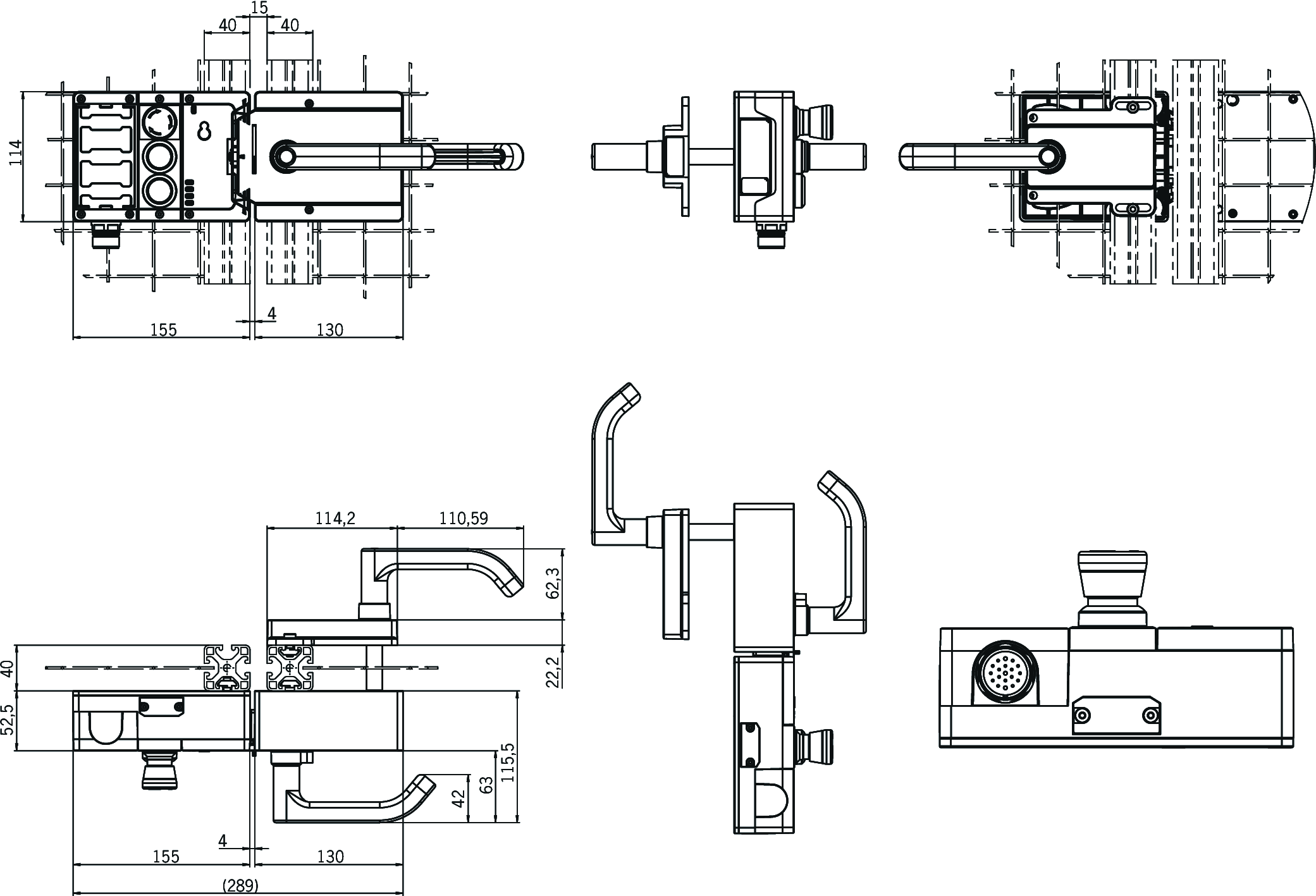
Dimensional drawings

Dimensional drawings
Technical data
Approvals


Handle modules MGB2-H-BA1A3-R-136691 (Order no. 136691)
Mechanical values and environment
| Installation orientation | Door hinge DIN right |
| Degree of protection | IP65 |
| Ambient temperature | -30 ... +55 °C |
| Material | |
| Housing | Fiber glass reinforced plastic, nickel-plated die-cast zinc, stainless steel |
Miscellaneous
| Additional feature | with automatic lockout mechanism |
Locking modules MGB2-L1-BR-U-XB2S0-DB-R-158394 (Order no. 158394)
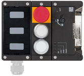
Mechanical values and environment
| Installation orientation | Door hinge DIN right |
Submodules MSM-1-K-CA-CPP-B2-137732

Operating and display elements
| Item | Color | Extras | Version | Switching element | Slide-in label | Note slide-in label | Number | Designation1 | LED |
|---|---|---|---|---|---|---|---|---|---|
| 1 | Emergency stop with monitoring contact | 2 PD + 1 NO | |||||||
| 2 | Illuminated pushbutton | 1NO | |||||||
| 3 | Illuminated pushbutton | 1NO |
Electrical connection values
| Current consumption | max. 24 mA |
| Controls and indicators | |
| Breaking capacity | max. 0.25 W |
| Switching voltage | 24 V |
| Switching current | 5 ... 10 mA |
| LED power supply | 24 V DC |
| Emergency stop | |
| Breaking capacity | max. 0.25 W |
| Switching voltage | 5 ... 24 V |
| Switching current | 1 ... 100 mA |
Mechanical values and environment
| Installation orientation | any |
| Shock and vibration resistance | Acc. to EN IEC 60947-5-3 |
| Degree of protection | IP65 (IP20) (when installed) |
| Ambient temperature | |
| with UB = 24 V DC | -25 ... +55 °C |
| Material | Fiber glass reinforced plastic |
Characteristic values according to EN ISO 13849-1 and EN IEC 62061
| B10D | Mission time | |
|---|---|---|
| Emergency stop | 0.13x10⁶ | 20 y |
Miscellaneous
| Submodulbreite | 1 |
| Additional feature | incl. lens set, ID no. 120344 |
Modules MGB2-L1-BR-U-X0000-BJ-158166
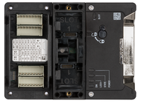
Electrical connection values
| Connection cross section | |
| (rigid/flexible) with cable end sleeve according to DIN 46 228/1 | 0.25 ... 1.5 mm² |
| (rigid/flexible) with cable end sleeve with collar according to DIN 46 228/1 | 0.25 ... 0.75 mm² |
| (rigid/flexible) | 0.25 ... 1.5 mm² ((AWG 23 ... AWG 16)) |
| Rated insulation voltage Ui | 75 V |
| Rated impulse withstand voltage Uimp | 1.5 kV |
| Discrepancy time | |
| between FO1A and FO1B | max. 10 ms |
| Utilization category | |
| DC-13 | 24 V 150 mA (Caution: outputs must be protected with a free-wheeling diode in case of inductive loads.) |
| Risk time according to EN 60947-5-3 | max. 50 ms |
| Risk time according to EN 60947-5-3, extension for each additional device | max. 10 ms |
| Safety class | III |
| Transponder coding | Unicode |
| Degree of contamination (external, according to EN 60947-1) | 3 |
| Monitoring outputs OD, OT/C, OL, OI | |
| Output type | Semiconductor outputs, p-switching, short circuit-proof |
| Output voltage | UB-2 ... UB V DC (Value at a switching current of 50mA without taking into account the cable lengths) |
| Output current | max. 50 mA |
| Safety outputs FO1A, FO1B | |
| Output type | Semiconductor outputs, p-switching, short circuit-proof |
| Output voltage | |
| UFO1A /UFO1B HIGH | UB-3,5 ... UB V DC (Value at a switching current of 150mA without taking into account the cable lengths) |
| UFO1A /UFO1B LOW | 0 ... 1 V DC |
| Output current | |
| per safety output FO1A / FO1B | 1 ... 150 mA |
| Turn-on time | max. 80 ms |
| Test pulse duration | max. 0.3 ms |
| Test pulse interval | min. 100 ms |
| Power supply UB | |
| Operating voltage DC | |
| UB | 24 V DC -15% ... +20% ((reverse polarity protected, regulated, residual ripple<5%, PELV)) |
| Current consumption | |
| IUB | max. 80 mA (at 20.4 V including safety inputs FI1A and FI1B, no load on outputs) |
| Power supply IMP, IMM | |
| Solenoid operating voltage DC | |
| UIMP | 24 V DC -15% ... +20% ((reverse polarity protected, regulated, residual ripple<5%, PELV)) |
| Current consumption | |
| IIMP | max. 375 mA |
| Test pulse duration | max. 5 ms |
| Test pulse interval | min. 100 ms |
Mechanical values and environment
| Connection type | Other connection option to X5 / X6 available |
| Ready delay | 5 s |
| Switching frequency | 0.25 Hz |
| Mechanical life | |
| Total | 1 x 10⁶ |
| in case of use as door stop, and 1 Joule impact energy | 0.2 x 10⁶ |
| when used as a door hinge and 2 joules of impact energy | 0.1 x 10⁶ |
| Shock and vibration resistance | Acc. to EN IEC 60947-5-3 |
| Degree of protection | IP65 (In the closed state when the connection cables, connecting cables and submodules are correctly mounted; assembly.) |
| Ambient temperature | |
| with UB = 24 V DC | -30 ... +55 °C |
| Material | |
| Housing | Fiber glass reinforced plastic; die-cast zinc, nickel plated |
| Locking force FZh | 2000 N |
| Guard locking principle | Closed-circuit current principle |
Characteristic values according to EN ISO 13849-1 and EN IEC 62061
| PL | Maximum SIL | PFHD | Category | Mission time | |
|---|---|---|---|---|---|
| Control of guard locking | PL e | 3 | 2.95x10⁻⁹ | 4 | 20 y |
| Monitoring of the guard position | PL e | 3 | 2.95x10⁻⁹ | 4 | 20 y |
| Monitoring of guard locking | PL e | 3 | 2.95x10⁻⁹ | 4 | 20 y |
Miscellaneous
| Slotkonfiguration | 1 |
Submodules MSM-C-K-BA-SBS-S0-160847

Mechanical values and environment
| Connection type | Cable entries M20x1.5 |
| Installation orientation | any |
| Shock and vibration resistance | Acc. to EN IEC 60947-5-3 |
| Degree of protection | IP65 (IP20) (when installed) |
| Ambient temperature | -25 ... +55 °C |
| Material | Fiber glass reinforced plastic |
Miscellaneous
| Slide-in label | |||||||
| |||||||
| Additional feature | |||||||
| incl. socket connector set, ID no. 136572 | |||||||
| Incl. label holder, ID no. 156733 | |||||||
Connection accessories AC-MC-00-0-B-156718
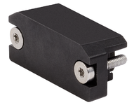
Electrical connection values
| Degree of contamination according to EN 60664-1 | 3 |
Mechanical values and environment
| Ambient temperature | -30 ... +55 °C |
| Material | Fiber glass reinforced plastic |
| Connection 1 | |
| Connection type | 2x M4 screws |
| Degree of protection | IP65 (Only in the screwed tight state with the specified base units.) |
Miscellaneous
| Color | black |
| Additional feature | |
| incl. fixing screws | |
| incl. seal |
Components

136691
MGB2-H-BA1A3-R-136691
Handle module MGB2-H... (door handle, with automatic lockout mechanism, door hinge on right)
MGB2-H-BA1A3-R-136691
Handle module MGB2-H... (door handle, with automatic lockout mechanism, door hinge on right)
- Intelligent bolt tongue
- Fold-out lockout mechanism
- Second automatically extending lockout mechanism
- Door handle
- Adjustable door hinge; factory setting: right

158394
MGB2-L1-BR-U-XB2S0-DB-R-158394
Locking module MGB2-L1-BR... (2 pushbuttons, emergency stop, closed-circuit current principle, door hinge on right)
MGB2-L1-BR-U-XB2S0-DB-R-158394
Locking module MGB2-L1-BR... (2 pushbuttons, emergency stop, closed-circuit current principle, door hinge on right)
- Guard locking with guard lock monitoring
- Emergency stop according to ISO 13850
- 2 illuminated pushbuttons
- 3 adhesive labels
- Cable entry M20 x 1.5 (order cable gland separately)
- Adjustable door hinge; factory setting: right
- Unicode
Accessories
Connection material
Function expansion
Escape release MGB-E-A...


100465
MGB-E-A-100465
MGB-E-A-100465
- Escape release from the danger zone
- Signal red door handle
- Designed for door profiles up to 40 mm
- Extended actuation axis for thicker doors (available optionally)

163885
MGB-E-A4-163885
MGB-E-A4-163885
- Escape release from the danger zone
- Signal red door handle
- Designed for door profiles up to 45 mm
- Extended actuation axis for thicker doors (available optionally)
Escape release module MGB-E... pre-assembled on mounting plate


106051
MGB-E-A2-106051
MGB-E-A2-106051
- Escape release from the danger zone
- Mounted on mounting plate
- Signal red door handle
- Designed for door profiles up to 40 mm
- Extended actuation axis for thicker doors (available optionally)

126320
MGB-E-A8-126320
MGB-E-A8-126320
- Escape release from the danger zone
- Mounted on mounting plate
- Signal red door knob
- Designed for door profiles up to 40 mm
- Extended actuation axis for thicker doors (available optionally)
Lock for auxiliary release for safety switch CTP/CTA/TP/STP


084177
AE-K-A1-DULK1-84177
AE-K-A1-DULK1-84177
- Lock unique locking
- Key removable in “unlocked” and “locked” positions

086236
AE-K-A1-IULK1-86236
AE-K-A1-IULK1-86236
- Identical locking
- Key removable in “unlocked” and “locked” positions

109212
AE-K-A1-IUK2-109212
AE-K-A1-IUK2-109212
- Identical locking
- Key can be removed only in “unlocked” position

121917
AE-K-A1-ILK1-121917
AE-K-A1-ILK1-121917
- Identical locking
- Key removable in “locked” position
Miscellaneous
Mounting accessories
Mounting plate for handle module MGB2-H...


156683
AM-P-H-156683
AM-P-H-156683
- For handle module MGB2-H
- Easy and quick mounting
- Quick module replacement
- Steel, powder coated
- Suitable for doors hinged on the right and left
- incl. screw set

173089
AM-P-H-173089
AM-P-H-173089
- For handle module MGB2-H
- Easy and quick mounting
- Quick module replacement
- Steel, powder coated
- Suitable for doors hinged on the right and left
- incl. screw set
Downloads
Complete package
Download all important documents with a single click.
Content:
- The operating instructions and any additions to the operating instructions or brief instructions
- Any data sheets to supplement the operating instructions
- The declaration of conformity
Single Documents
Data sheets
Data sheet


Doc. no.
Version
Language
Size

Data sheet
Fiche technique
Ficha de datos
Datenblatt
Ficha de dados
数据表
データ シート
데이터 시트
Datový list
Fiche technique
Ficha de datos
Datenblatt
Ficha de dados
数据表
データ シート
데이터 시트
Datový list
Doc. no.
Version
02
Language
Size
0,2 MB

Data sheet
Fiche technique
Ficha de datos
Datenblatt
Ficha de dados
数据表
データ シート
데이터 시트
Datový list
Fiche technique
Ficha de datos
Datenblatt
Ficha de dados
数据表
データ シート
데이터 시트
Datový list
Doc. no.
Version
03
Language
Size
0,2 MB

Data sheet
Fiche technique
Ficha de datos
Datenblatt
Ficha de dados
数据表
データ シート
데이터 시트
Datový list
Fiche technique
Ficha de datos
Datenblatt
Ficha de dados
数据表
データ シート
데이터 시트
Datový list
Doc. no.
Version
03
Language
Size
0,2 MB

Data sheet
Fiche technique
Ficha de datos
Datenblatt
Ficha de dados
数据表
データ シート
데이터 시트
Datový list
Fiche technique
Ficha de datos
Datenblatt
Ficha de dados
数据表
データ シート
데이터 시트
Datový list
Doc. no.
Version
01
Language
Size
0,1 MB
Declarations of conformity
EU-Konformitätserklärung

Doc. no.
Version
Language
Size

EU-Konformitätserklärung
Doc. no.
EDC2500504
Version
Language
Size
0,2 MB
UKCA-Konformitätserklärung

Doc. no.
Version
Language
Size

UKCA-Konformitätserklärung
Doc. no.
EDC20001507
Version
Language
Size
0,1 MB
Instructions
Operating Instructions Safety Systems MGB2-L1…-BR.-… / MGB2-L2…-BR.-… and MGB2-L1…-BP.-… / MGB2-L2…-BP.-…


Doc. no.
Version
Language
Size

Operating Instructions Safety Systems MGB2-L1…-BR.-… / MGB2-L2…-BR.-… and MGB2-L1…-BP.-… / MGB2-L2…-BP.-…
Doc. no.
2500233
Version
02/23
Language
Size
7,5 MB

Mode d’emploi Systèmes de sécurité MGB2-L1…-BR.-… / MGB2-L2…-BR.-… et MGB2-L1…-BP.-… / MGB2-L2…-BP.-…
Doc. no.
2500233
Version
02/23
Language
Size
7,5 MB

Betriebsanleitung Sicherheitssysteme MGB2-L1…-BR.-… / MGB2-L2…-BR.-… und MGB2-L1…-BP.-… / MGB2-L2…-BP.-…
Doc. no.
2500233
Version
02/23
Language
Size
7,5 MB

Návod k použití Bezpečnostní systémy MGB2-L1…-BR.-… / MGB2-L2…-BR.-… a MGB2-L1…-BP.-… / MGB2-L2…-BP.-…
Doc. no.
2500233
Version
02/23
Language
Size
7,8 MB
Other Documents
Application examples
Approvals and certificates
FCC

Doc. no.
Version
Language
Size

FCC
Doc. no.
Version
Language
Size
0,2 MB
Sales documents
Multifunctional door locking systems MGB2


Doc. no.
Version
Language
Size

Multifunctional door locking systems MGB2
Doc. no.
159039
Version
04-06/19
Language
Size
21,1 MB

Systèmes de gestion d‘accès multifonctionnels MGB2
Doc. no.
159050
Version
04-06/19
Language
Size
21,1 MB

Sistemas de cierre de puertas multifuncionales MGB2
Doc. no.
159051
Version
04-06/19
Language
Size
21,2 MB

Multifunktionale Türschließsysteme MGB2
Doc. no.
159037
Version
04-06/19
Language
Size
21,1 MB
Ordering data
| Ordernumber | 161774 |
| Item designation | MGB2-L1H-BR-U-S0-DB-R-161774 |
| Gross weight | 2,605kg |
| Customs tariff number | 85371098 |
| ECLASS | 27-27-24-05 Safety-related transponder switch with guardlocking |


