ZSM2104-167826 (Order no. 167826)
ZSM, LED, + and - buttons, vibration motor, stop command device, key-operated rotary switch
- 3-stage function
- Stop command device
- Vibration signal
- LED indicator
- + and – buttons
- Key-operated rotary switch; key can be removed in 0 position
- Straight connecting cable, 5 m

Description
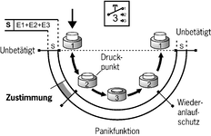
3-stage function
Enabling function is active only in the second stage (center position, actuating point). If the pushbutton is released or pushed further (panic function), the enabling is removed (dependent on the wiring, see function sequence).
Stop command device
Dual-channel emergency stop device (red, with pull-to-reset and turn-to-reset button) on the switch housing, for different wiring concepts.
Lower position, protected by anti-kink strain relief in case of a fall.
Vibration signal
The vibration signal is used for tactile feedback of the enabling position.
LED indicator
The LED indicator is used for visual feedback directly at the enabling switch.
+ and – buttons
These pushbuttons can be configured individually. For example, for moving axes in the positive or negative direction.
Key-operated rotary switch
For individual use, e.g. as an operating mode selector. Key can be removed in 0 position.
Cable
The high-quality connecting cables are available in a straight version.

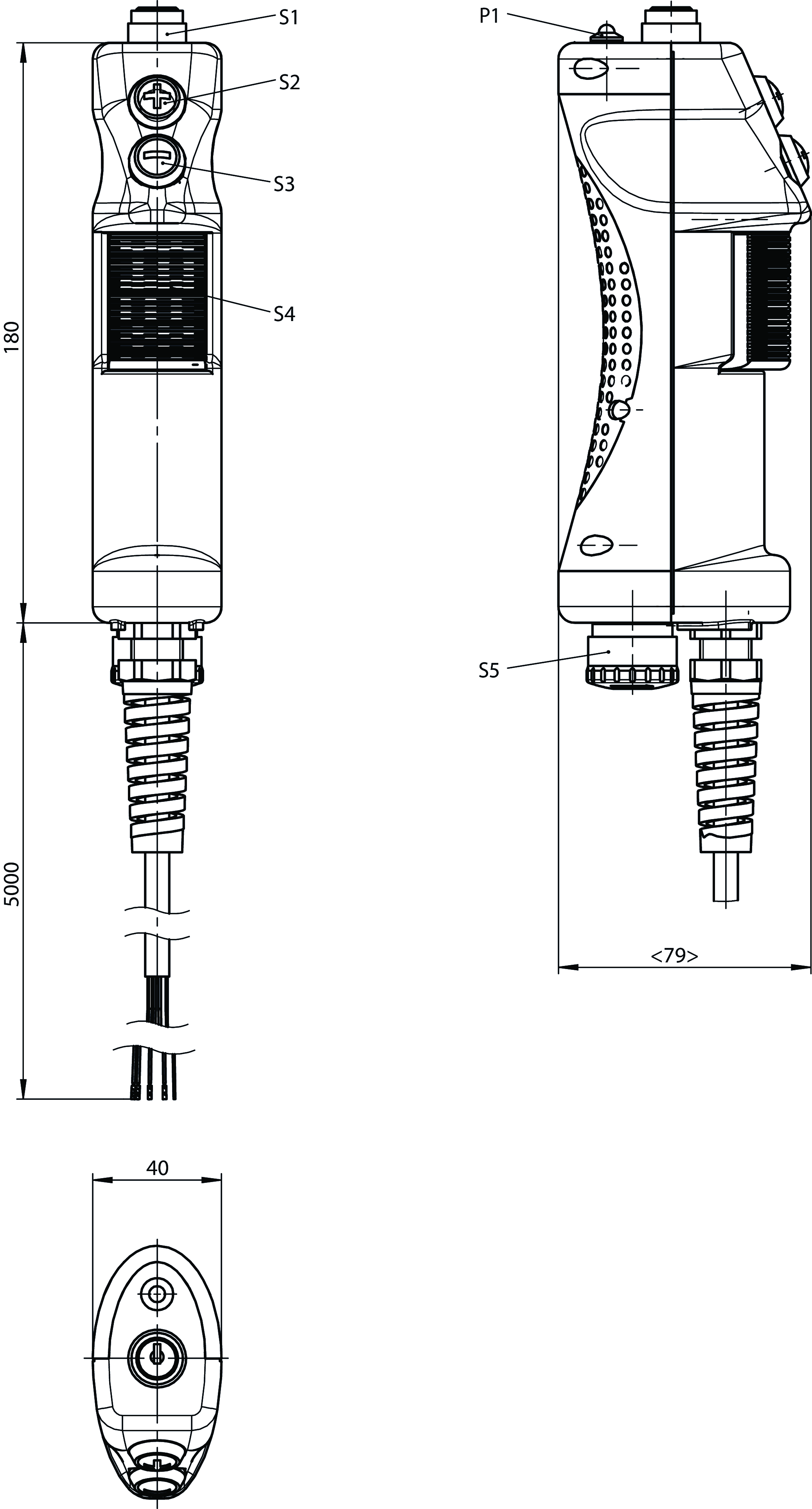
Dimensional drawings
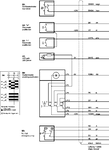
Connection examples
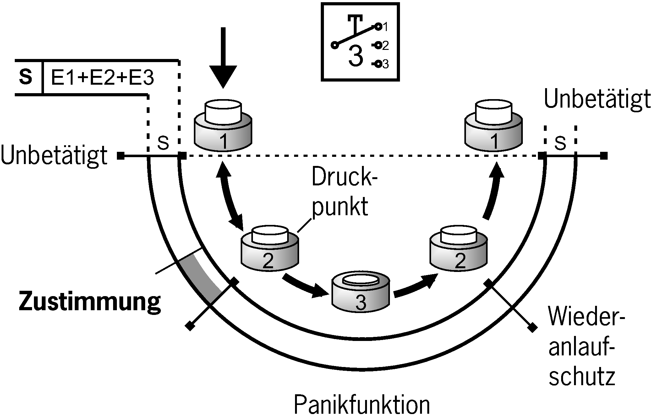
Connection examples
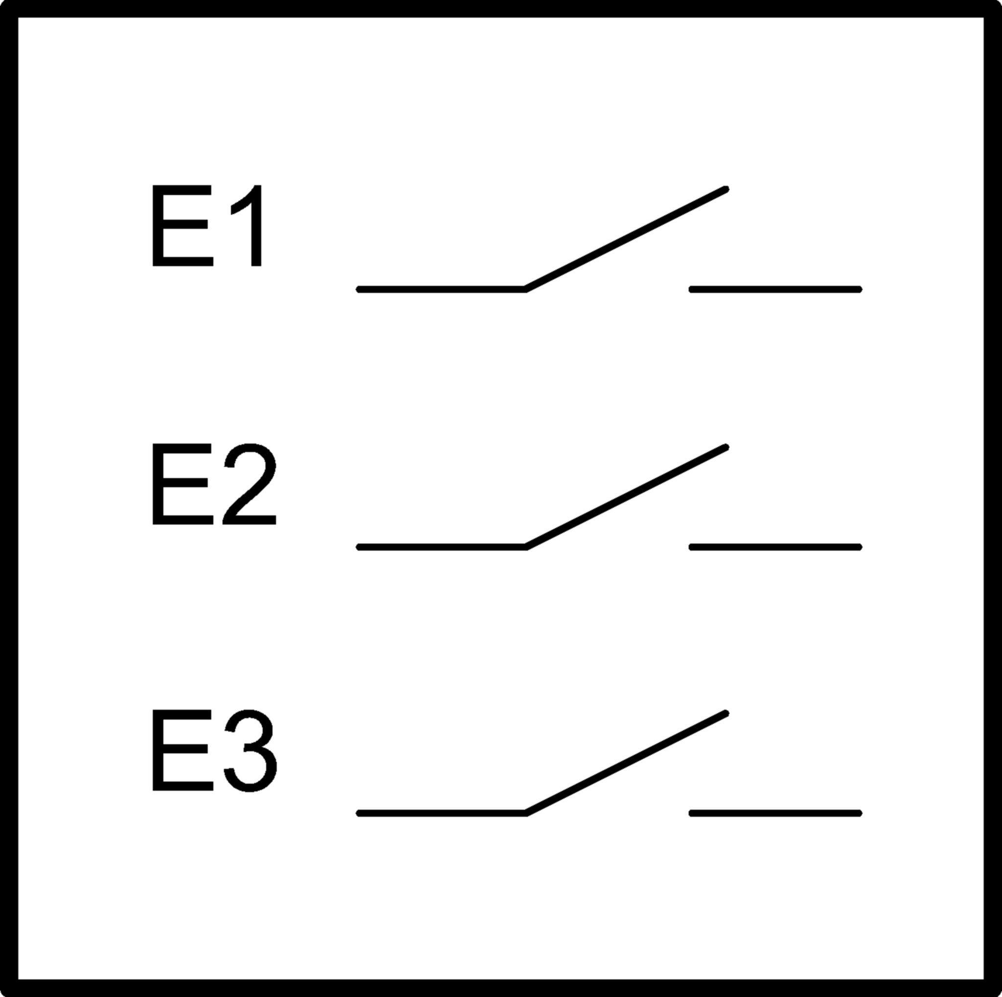
Connection examples
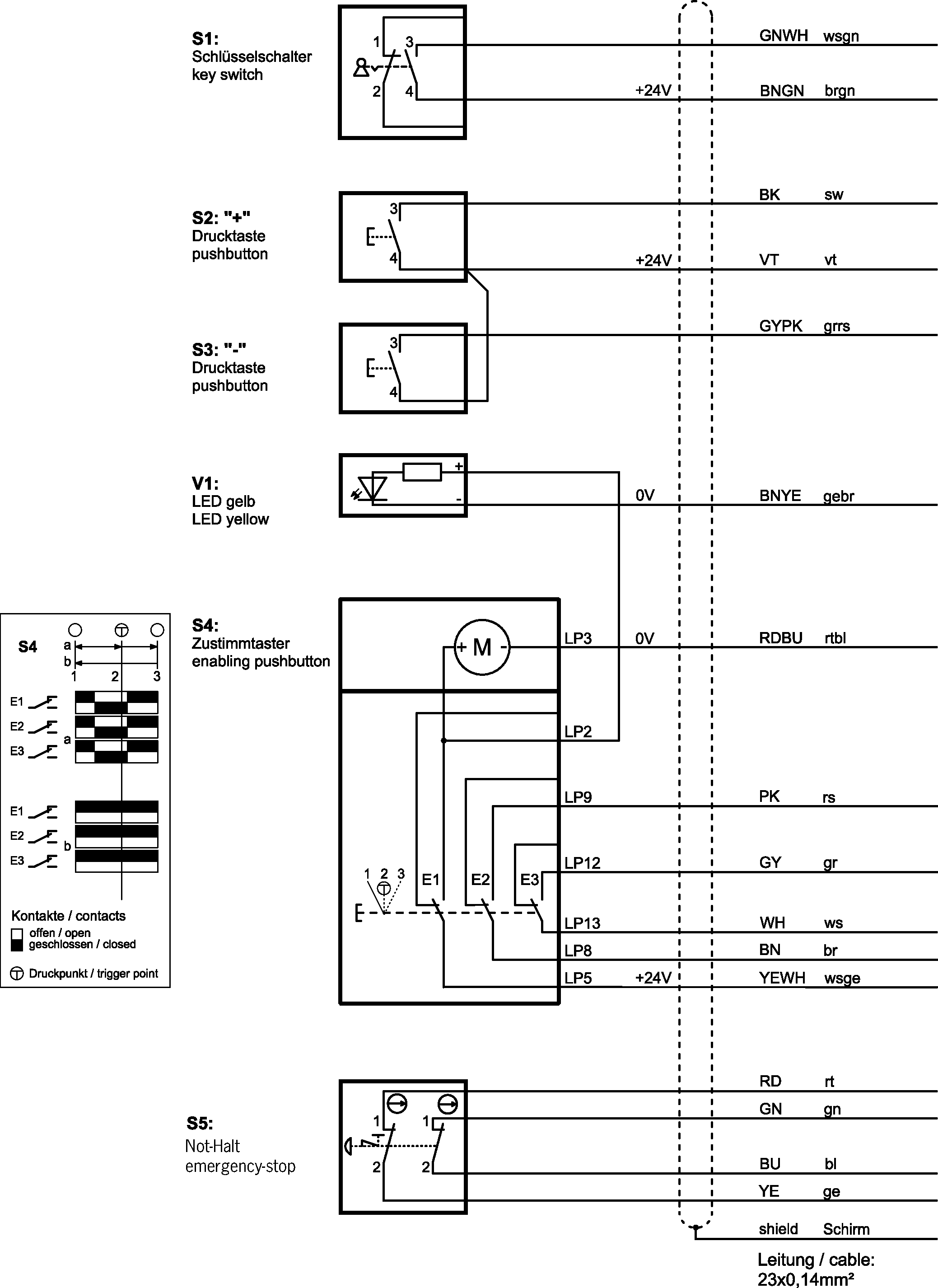
Technical data
Approvals


Operating and display elements
| Item | Color | Extras | Version | Note slide-in label | Switching element | Slide-in label | Number | Designation1 | LED |
|---|---|---|---|---|---|---|---|---|---|
| Vibration motor | 1 | ||||||||
| Key can be removed in center position | Key-operated rotary switch | 1 | |||||||
| Emergency stop device | 1 | ||||||||
| + button | 1 | ||||||||
| - button | 1 | ||||||||
| Yellow | LED | 1 |
Electrical connection values
| Connecting cable | 23x0.14 mm² (screened) |
| rated conditional short-circuit current | 100 A |
| Rated insulation voltage Ui | 50 V |
| Rated impulse voltage Uimp | 0.5 kV |
| Utilization category | |
| DC-13 | 24 V 0.3 A (For additional controls) |
| DC-13 | 30 V 0.1 A (For enabling switch, caution: outputs must be protected with a free-wheeling diode in case of inductive loads) |
| DC-13 | 24 V 0.01 A (For additional indicators) |
| Short circuit protection according to IEC 60269-1 | 2A gG (In case of operating voltages other than 24 V, the short circuit protection must be dimensioned accordingly and checked.) |
| Switching characteristics | 3-stage enabling switch |
| Degree of contamination (external, according to EN 60947-1) | 3 |
Mechanical values and environment
| Connection type | Flying lead with cable end sleeves |
| Number of changeover contacts | 3 (Connection as per block diagram) |
| Cable length | |
| straight | 5 m |
| Mechanical life | 1 x 10⁶ |
| Switching principle | Snap-action contact element |
| Degree of protection | IP54 |
| Ambient temperature | -5 ... +60 °C |
| Material | PA, CR, TPE (Low PAH) |
Characteristic values according to EN ISO 13849-1 and EN IEC 62061
| Emergency stop | |
| B10D | 0.1 x 10⁶ |
| Enabling switch | |
| B10D | 0.1 x 10⁶ |
Miscellaneous
| in compliance with | 60947-5-8 |
Accessories
Downloads
Complete package
Download all important documents with a single click.
Content:
- The operating instructions and any additions to the operating instructions or brief instructions
- Any data sheets to supplement the operating instructions
- The declaration of conformity
Single Documents


Mode d’emploi Commande d’assentiment ZSM
Manual de instrucciones Pulsador de validación ZSM
Betriebsanleitung Zustimmtaster ZSM


Other Documents

Ordering data
| Ordernumber | 167826 |
| Item designation | ZSM2104-167826 |
| Gross weight | 0,95kg |
| Customs tariff number | 85371098 |
| ECLASS | 27-37-12-38 Agreement switch |


