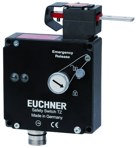
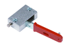
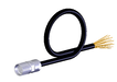
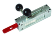
Safety switch TZ, plug connector M23 (RC18), emergency unlocking with rotary knob, escape release with pushbutton, special wiring
- Plug connector M23 (RC18)
- Escape release with pushbutton
- Emergency unlocking with rotary knob
- LED indicator
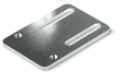
- Protective plate for switch head
- Actuating head fitted right
- Closed-circuit current principle
Description
Approach direction
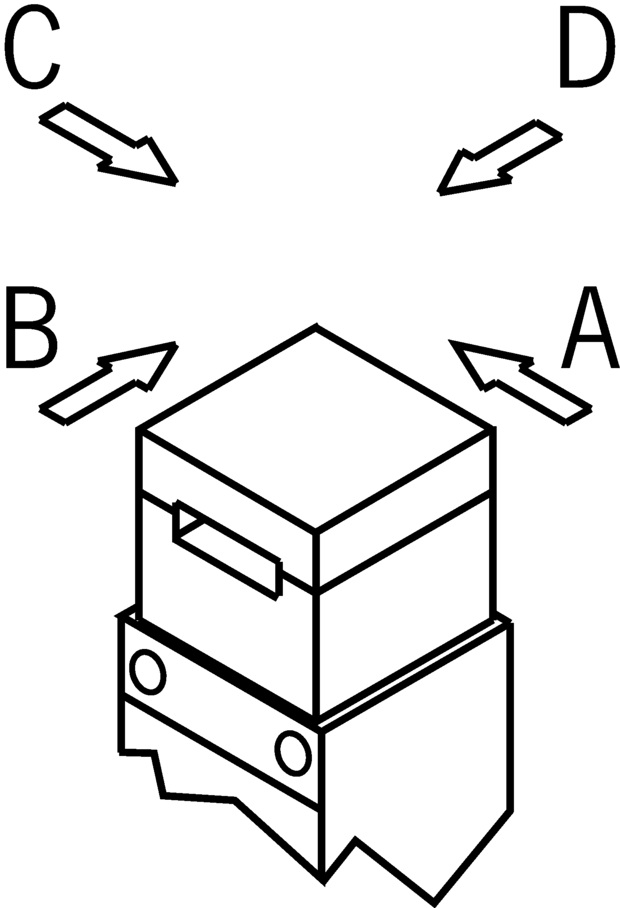
Horizontal
Can be adjusted in 90° steps
Guard locking principle
closed-circuit current (power to unlock): In a safety guard with guard locking according to the closed-circuit current principle, the guard is locked by spring force until the guard locking solenoid is supplied with current. The guard is unlocked by means of magnetic force. This is also referred to as mechanical guard locking.
Protective plate for switch head
Makes tampering with the switch more difficult.
LED indicator
The switch has two freely assignable LED indicators (red and green).
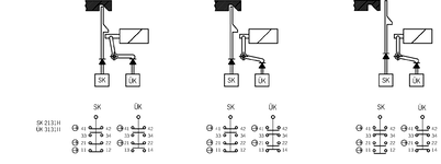
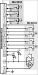
Switching element
SK | 2131 | Slow-action switching contact |
Contacts for door monitoring: 2 positively driven, positively driven contacts | ||
ÜK | 3131 | Slow-action switching contact |
Contacts for guard locking: 2 positively driven, positively driven contacts |
 1 NO contact
 2 NO contacts
Emergency release
The emergency unlocking on the front is used to unlock the guard locking without tools in the event of danger. Unblocking and restoring readiness for operation requires an effort comparable to a repair. A sealing can be attached to prevent tampering.
Escape release
This is used for manual release of guard locking from the danger zone without tools.
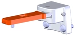
Required accessories
Actuator is not included in the scope of delivery.
Functional drawings

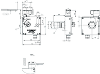
Dimensional drawings
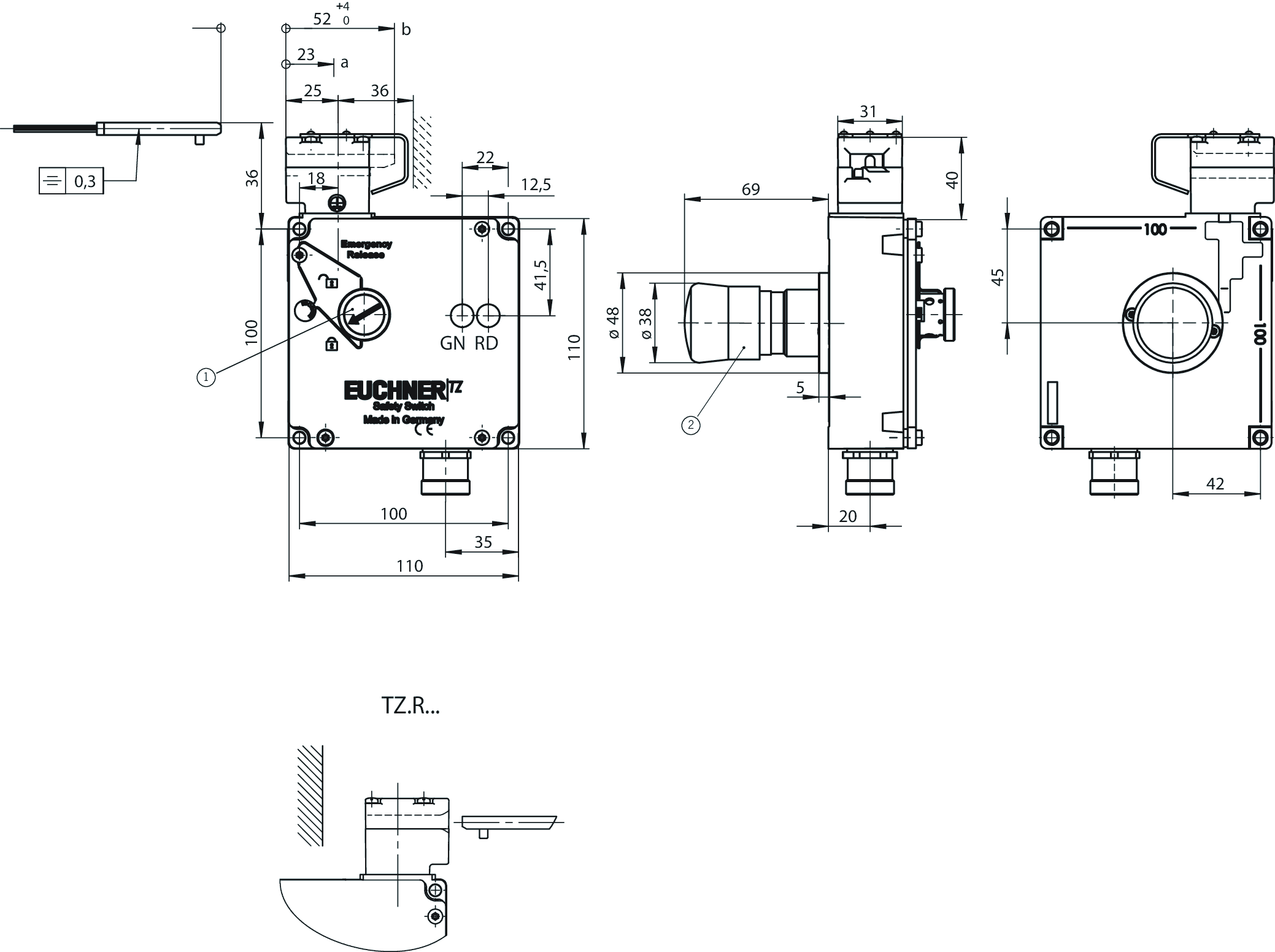
| 1 | Emergency unlocking (rotary knob) |
| 2 | Escape release (pushbutton) |
Connection examples
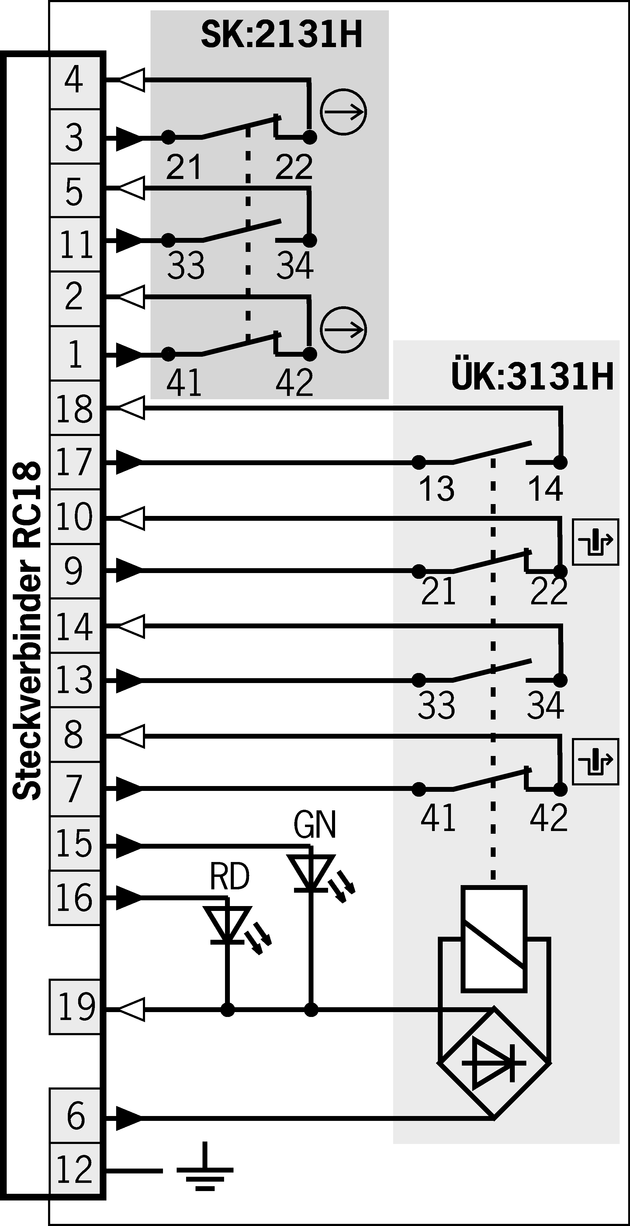
 | Door monitoring |
 | Solenoid monitoring |
Technical data
Approvals


Operating and display elements
| LED display | Operating voltage corresponds to the solenoid voltage (2 LEDs; green, red) |
Electrical connection values
| Power consumption | 10 W |
| Rated insulation voltage Ui | 50 V |
| Rated impulse withstand voltage Uimp | 1.5 kV |
| Utilization category | |
| DC-13 | 4 A 24 V (>70 °C =>2 A) |
| AC-15 | 4 A 50 V (>70 °C =>2 A) |
| Short circuit protection according to IEC 60269-1 | 4A gG (> 70 °C => 2A gG) |
| Solenoid operating voltage | |
| AC/DC | 24 V -15% ... +10% |
| Solenoid duty cycle | 100 % |
| Switching voltage | |
| min. at 10 mA | 12 V |
| Switching current | |
| min. at 24 V | 1 mA |
| thermal rated current Ith | 4 A (>70 °C =>2 A) |
Mechanical values and environment
| Approach speed | max. 20 m/min |
| Approach direction | |
| Actuating head on the right | A |
| Connection type | |
| 1 x | Plug connector RC18 (18 + PE) |
| Number of door position NO contacts | 1 |
| Number of guard lock monitoring NO contacts | 2 |
| Number of door position positively driven contacts | 2 |
| Number of guard lock monitoring positively driven contacts | 2 |
| Extraction force | 30 N |
| Actuation frequency | max. 1200 1/h |
| Actuating force | 35 N |
| Lid | black |
| Installation orientation | any |
| Insertion depth | 52 mm |
| Mechanical life | 1 x 10⁶ |
| Retention force | 10 N |
| Switching principle | Slow-action switching contact |
| Degree of protection | IP65 |
| Ambient temperature | -25 ... +80 °C |
| Material | |
| Contact | Silver alloy, gold flashed |
| Housing | Anodized die-cast alloy |
| Locking force Fmax | 2000 N |
| Locking force FZh | 1500 N |
| Guard locking principle | Closed-circuit current principle |
Characteristic values according to EN ISO 13849-1 and EN IEC 62061
| B10D | Mission time | |
|---|---|---|
| Monitoring of the guard position | 3x10⁶ | 20 y |
| Important! Values valid at DC-13 100 mA/24V | ||
| Monitoring of guard locking | 3x10⁶ | 20 y |
| Important! Values valid at DC-13 100 mA/24V | ||
| PL | Maximum SIL | Category | Mission time | |
|---|---|---|---|---|
| Control of guard locking | Depending on external control of guard locking | 20 y | ||
Miscellaneous
| C number | |
| C2123 | with auxiliary release, escape release and protective plate |
In combination with actuator ACTUATOR-Z-GN
| Overtravel | 16 mm |
In combination with actuator ACTUATOR-Z-G
| Overtravel | 4 mm |
Accessories

BETAETIGER-Z-G
- Two stainless-steel safety screws per actuator
BETAETIGER-Z-G/V25
- Two stainless-steel safety screws per actuator
- Packaging unit 25 pieces

BETAETIGER-Z-GN
- Two stainless-steel safety screws per actuator

BETAETIGER-Z-GME
- Made of solid stainless steel
- Two stainless-steel safety screws per actuator


Downloads
Complete package
Download all important documents with a single click.
Content:
- The operating instructions and any additions to the operating instructions or brief instructions
- Any data sheets to supplement the operating instructions
- The declaration of conformity
Single Documents

Déclaration UE de conformité
Declaración de conformidad UE
EU-Konformitätserklärung
Dichiarazione UE di conformità

Déclaration UE de conformité
Declaración de conformidad UE
EU-Konformitätserklärung
Dichiarazione UE di conformità


Mode d’emploi Interrupteur de sécurité TZ…
Manual de instrucciones Interruptor de seguridad TZ…
Betriebsanleitung Sicherheitsschalter TZ…


Other Documents


CAD data

Ordering data
| Ordernumber | 097348 |
| Item designation | TZ1RE024RC18VAB-C2123 |
| Gross weight | 1,429kg |
| Customs tariff number | 85365019000 |
| ECLASS | 27-27-26-03 Safety switch with guard control |
