Non-contact safety switch CES-A-C5...
- Safety switch with integrated evaluation electronics
- Pulsed signals can be switched
- 2 safety outputs (semiconductor outputs)
- Category 3 / PL e according to EN ISO 13849-1
- Unicode
Description
Approach direction
Can be adjusted in 90° steps
Unicode evaluation
Each actuator is highly coded (unicode). The switch detects only taught-in actuators. Additional actuators can be taught-in.
Category according to EN ISO 13849-1
Due to two redundantly designed semiconductor outputs (safety outputs) with internal monitoring suitable for:
- Category 3 / PL e according to EN ISO 13849-1
LED indicator
STATE | Status LED |
OUT/ERROR | Safety outputs status / diagnostics LED (combined) |
Additional connection
OUT | Monitoring output (semiconductor) |
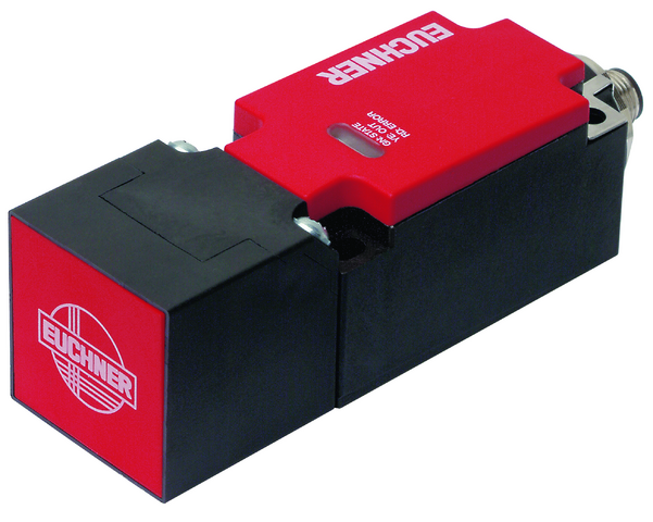
Typical actuating ranges
Attention:
The actuating range may vary depending on the substrate material and installation situation.
Typical actuating range
(Only in combination with actuator CES-A-BBA, CES-A-BCA)
For a side approach direction for the actuator and safety switch, a minimum distance of s = 4 mm must be maintained so that the actuating range of the side lobes is not entered.
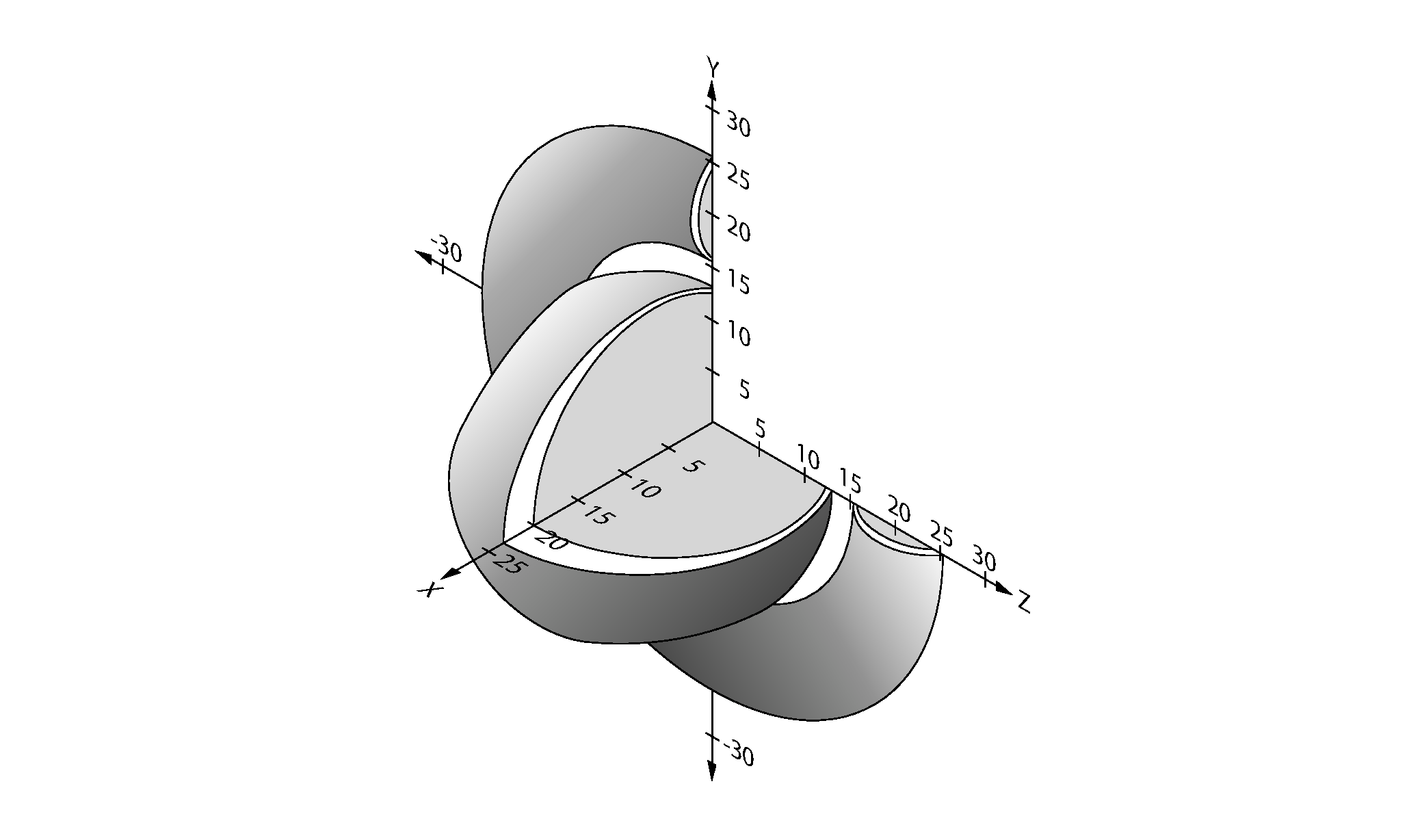
Typical actuating range
(Only in combination with actuator CES-A-BPA)
For a side approach direction for the actuator and safety switch, a minimum distance of s = 6 mm must be maintained so that the actuating range of the side lobes is not entered.
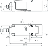
Dimensional drawings
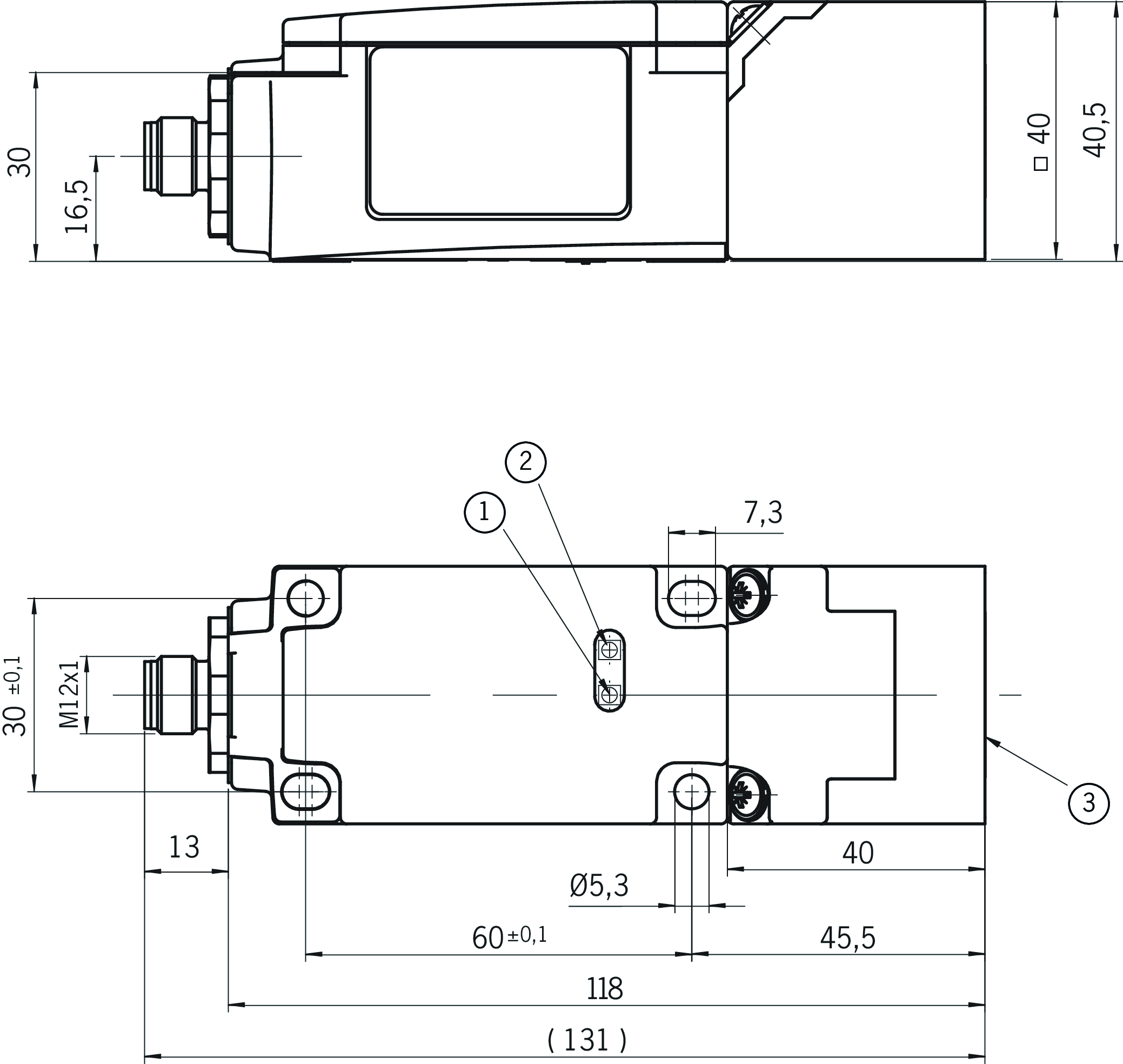
| 1 | LED status indication |
| 2 | LED status indication |
| 3 | Active face |
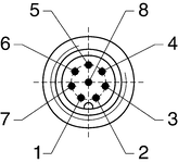
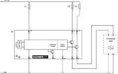
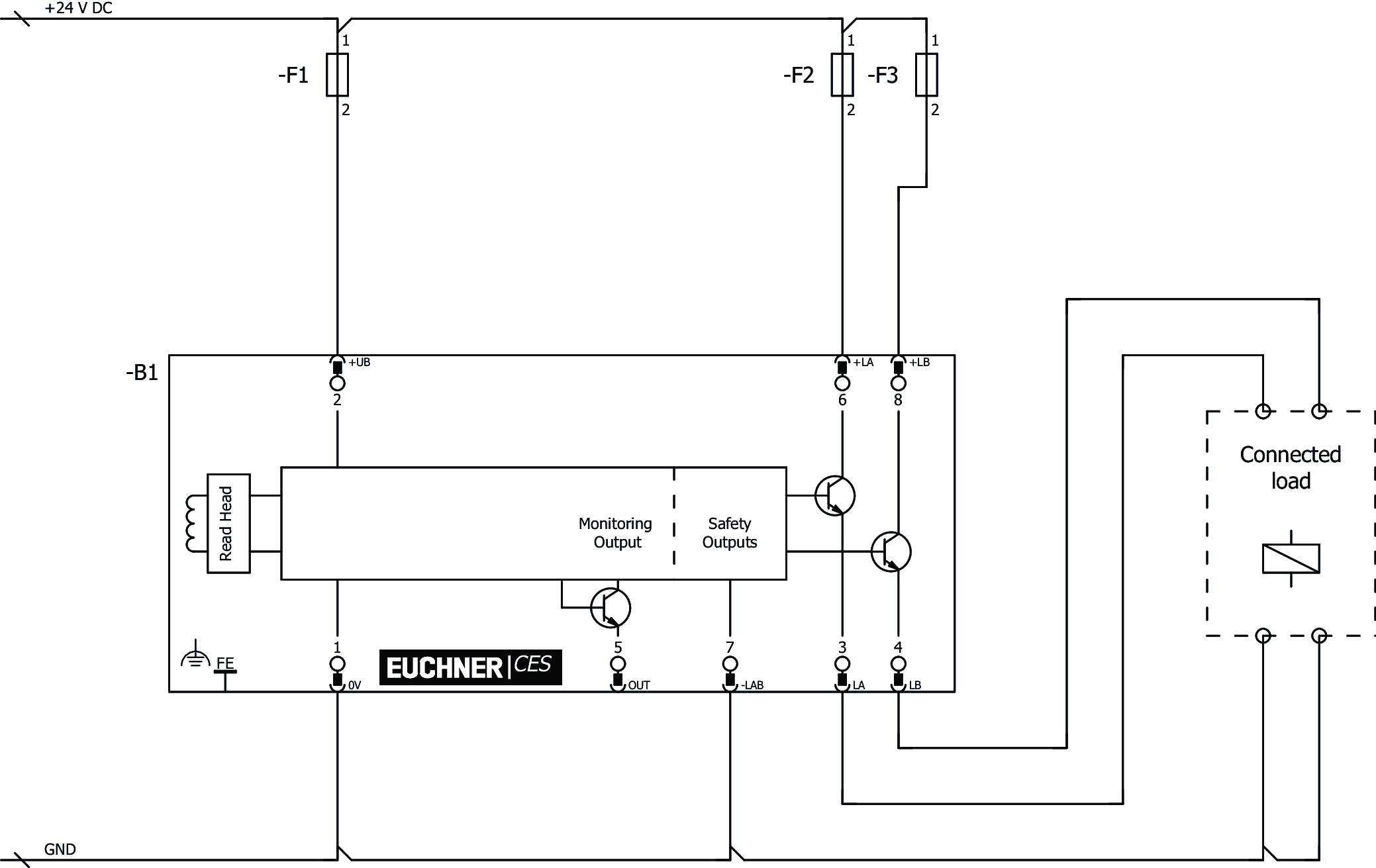
Connection examples
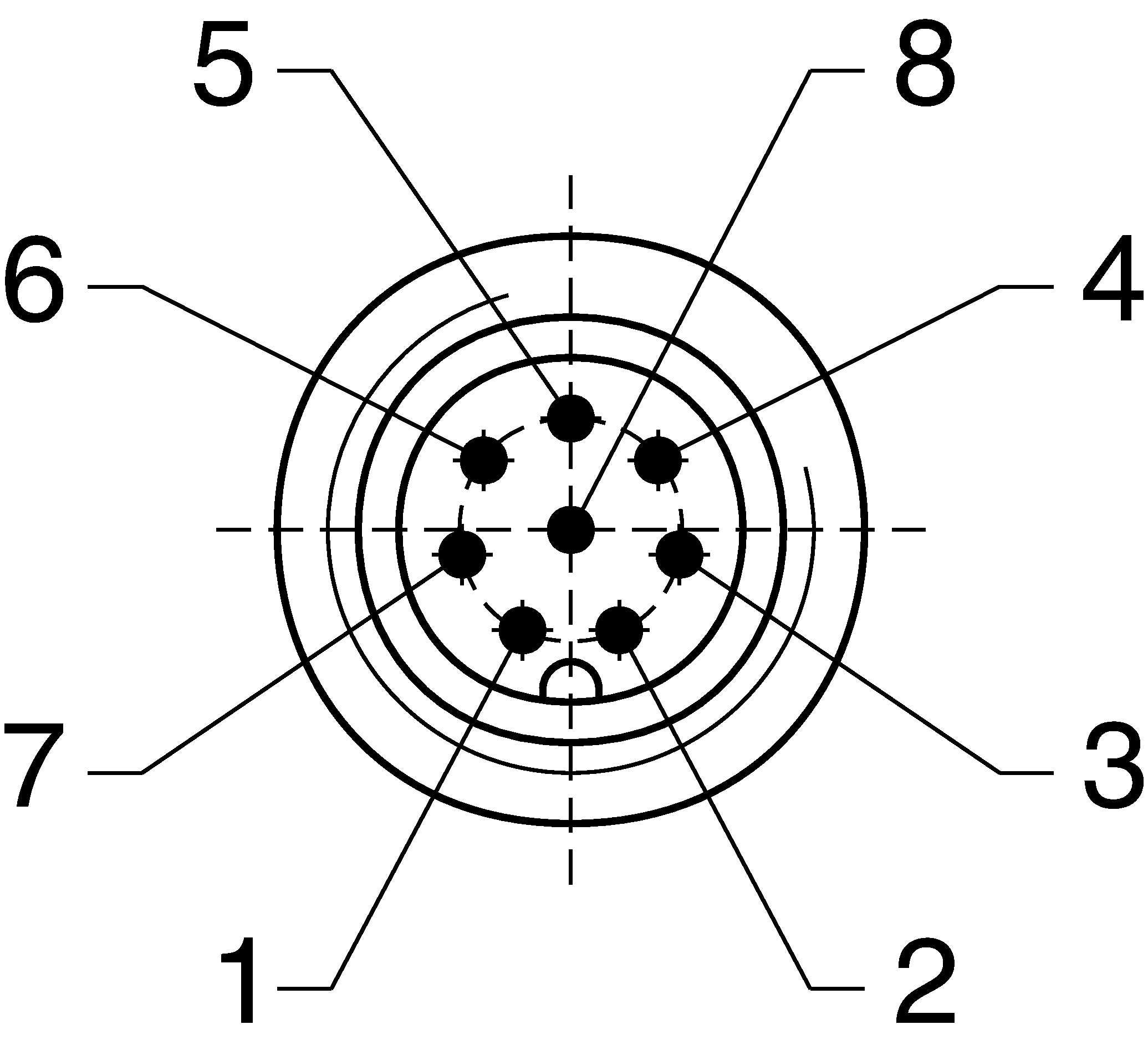
Connection examples
Technical data
Approvals


Workspace
| Repeat accuracy R | |
| according to EN 60947-5-2 | max. 10 % |
Operating and display elements
| LED display | |
| Safety outputs status / diagnostics LED (combined) | |
| Status LED |
Electrical connection values
| Fuse | |
| (external) operating voltage | 0.25 ... 8 A |
| Rated insulation voltage Ui | 75 V (Tested by the employers’ liability insurance association up to 75 V.) |
| Rated impulse withstand voltage Uimp | 1.5 kV |
| Operating voltage DC | 18 ... 24 ... 27 V DC regulated, residual ripple<5% |
| EMC protection requirements | Acc. to EN IEC 60947-5-3 |
| Current consumption | 80 mA |
| Degree of contamination (external, according to EN 60947-1) | 3 |
| Monitoring output OUT | |
| Output type | Semiconductor output, p-switching, short circuit-proof |
| Output voltage | 0.8 x UB ... UB V DC |
| Switching current | max. 20 mA |
| Safety outputs LA / LB | |
| Fuse | |
| external, safety circuit U(+LA) / U(+LB) | 0.4 A medium slow-blow |
| Output type | Semiconductor outputs, p-switching, short circuit-proof, electrically decoupled (To ensure safety, both safety outputs (LA and LB) must be evaluated.) |
| Output voltage | |
| HIGH U(LA) | U(+LA) - 1.5 ... U(+LA) V DC |
| LOW U(LA) / U(LB) | 0 ... 1 V DC |
| HIGH U(LB) | U(+LB) - 1.5 ... U(+LB) V DC |
| rated conditional short-circuit current | max. 100 A |
| Discrepancy time | |
| (between the operating points of both safety outputs) | max. 120 ms |
| Utilization category | |
| DC-13 Safety outputs LA / LB | 24 V 400 mA |
| Switching load | |
| according to UL | max. DC 24 V, Class 2 |
| Switching current | |
| per safety output | 1 ... 400 mA |
| Power supply output load | |
| U(+LA) / U(+LB) | 18 ... 24 ... 27 V DC |
Mechanical values and environment
| Dimensions | according to EN 60947-5-2: (LxWxH) 131x40x40 |
| Connection type | M12 plug connector, 8-pin; shield can be connected |
| Tightening torque | |
| Fixing screws, housing | max. 1 Nm |
| Screws, read head mounting bracket | max. 0.6 Nm |
| Ready delay | max. 3 s (After the operating voltage is switched on, the semiconductor outputs are switched off and the monitoring outputs are set to LOW level during the ready delay.) |
| Installation orientation | any |
| Switching frequency | max. 1 Hz |
| Mounting distance | |
| between switches | min. 80 mm |
| Response time | |
| after change in the actuation status | max. 180 ms (Corresponds to the risk time according to EN 60947-5-3. This is the maximum OFF time for the safety outputs following removal of the actuator.) |
| Degree of protection | IP65/IP67 |
| Ambient temperature | |
| with UB = 24 V DC | -20 ... +55 °C |
| Dwell time | min. 0.5 s (The dwell time of an actuator inside and outside the actuating range must be at least 0.5 s to ensure safe detection of internal faults in the evaluation unit (self-monitoring).) |
| Material | |
| Housing | Plastic, PBT |
Characteristic values according to EN ISO 13849-1 and EN IEC 62061
| PL | Maximum SIL | PFHD | Category | Mission time | |
|---|---|---|---|---|---|
| Monitoring of the guard position | PL e | - | 4.29x10⁻⁸ | 3 | 20 y |
Miscellaneous
| The following applies to the approval according to UL | Operation only with UL Class 2 power supply or equivalent measures |
In combination with actuator CES-A-BBA-071840, CES-A-BCA
| Actuator distance s | |
| Minimum distance for side approach direction | min. 4 mm |
| Switch-on distance | |
| with center offset m=0 | 20 mm (for non-flush mounting; assembly of the actuator) |
| Secured switch-off distance sar | max. 40 mm |
| Secured switching distance sao | |
| with center offset m=0 | min. 18 mm (for non-flush mounting; assembly of the actuator) |
| Switching hysteresis | 2 ... 3 mm (for non-flush mounting; assembly of the actuator) |
In combination with actuator CES-A-BDA-20
| Actuator distance s | |
| Minimum distance for side approach direction | min. 5 mm |
| Switch-on distance | |
| with center offset m=0 | 21 mm (in non-metallic environment) |
| Secured switch-off distance sar | max. 41 mm |
| Secured switching distance sao | |
| with center offset m=0 | min. 19 mm (in non-metallic environment) |
| Switching hysteresis | 2 ... 3 mm (in non-metallic environment) |
In combination with actuator CES-A-BPA-098775
| Actuator distance s | |
| Minimum distance for side approach direction | min. 6 mm |
| Switch-on distance | |
| with center offset m=0 | 22 mm (for non-flush mounting; assembly on aluminum; in a metal-free environment, the typical strand increases to 30 mm) |
| Secured switch-off distance sar | max. 58 mm |
| Secured switching distance sao | |
| with center offset m=0 | min. 15 mm (for non-flush mounting; assembly on aluminum) |
| Switching hysteresis | 1 ... 2 mm (for non-flush mounting; assembly on aluminum) |
Accessories


Downloads
Complete package
Download all important documents with a single click.
Content:
- The operating instructions and any additions to the operating instructions or brief instructions
- Any data sheets to supplement the operating instructions
- The declaration of conformity
Single Documents


Other Documents


CAD data

Ordering data
| Ordernumber | 077750 |
| Item designation | CES-A-C5E-01 |
| Gross weight | 0,35kg |
| Customs tariff number | 85365019000 |
| ECLASS | 27-27-24-03 Safety-related transponder switch |
