MGB-L2HEB-EIA-L-161480 (Rend. sz. 161480)
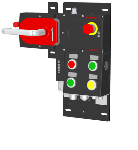
Locking set MGB-L2...-EI (guard locking by solenoid force) with 5 control elements, 7/8" and M12 plugs
- Guard locking with guard lock monitoring
- Emergency stop according to ISO 13850, illuminated
- 4 illuminated pushbuttons
- including adhesive labels
- Connection via 7/8" and M12 plugs
- including terminal plug for stack light (M12, 5-pin)
- Pre-assembled on mounting plates
- With escape release
- Unicode

Ismertetés
Ethernet/IP connection
7/8" and M12 plugs (d-coded)
Integrated switches
Integrated switches permit linear and DLR network structures
Flexible use as interlocking or guard locking
By means of the corresponding evaluation of the safe device data by the control system, use can be as either interlocking or guard locking (with or without monitoring).
Illuminated emergency stop
Emergency stop with illumination that can be controlled as required.
Escape release
The escape release enables people accidentally shut in to open the guard locked door from the danger zone.

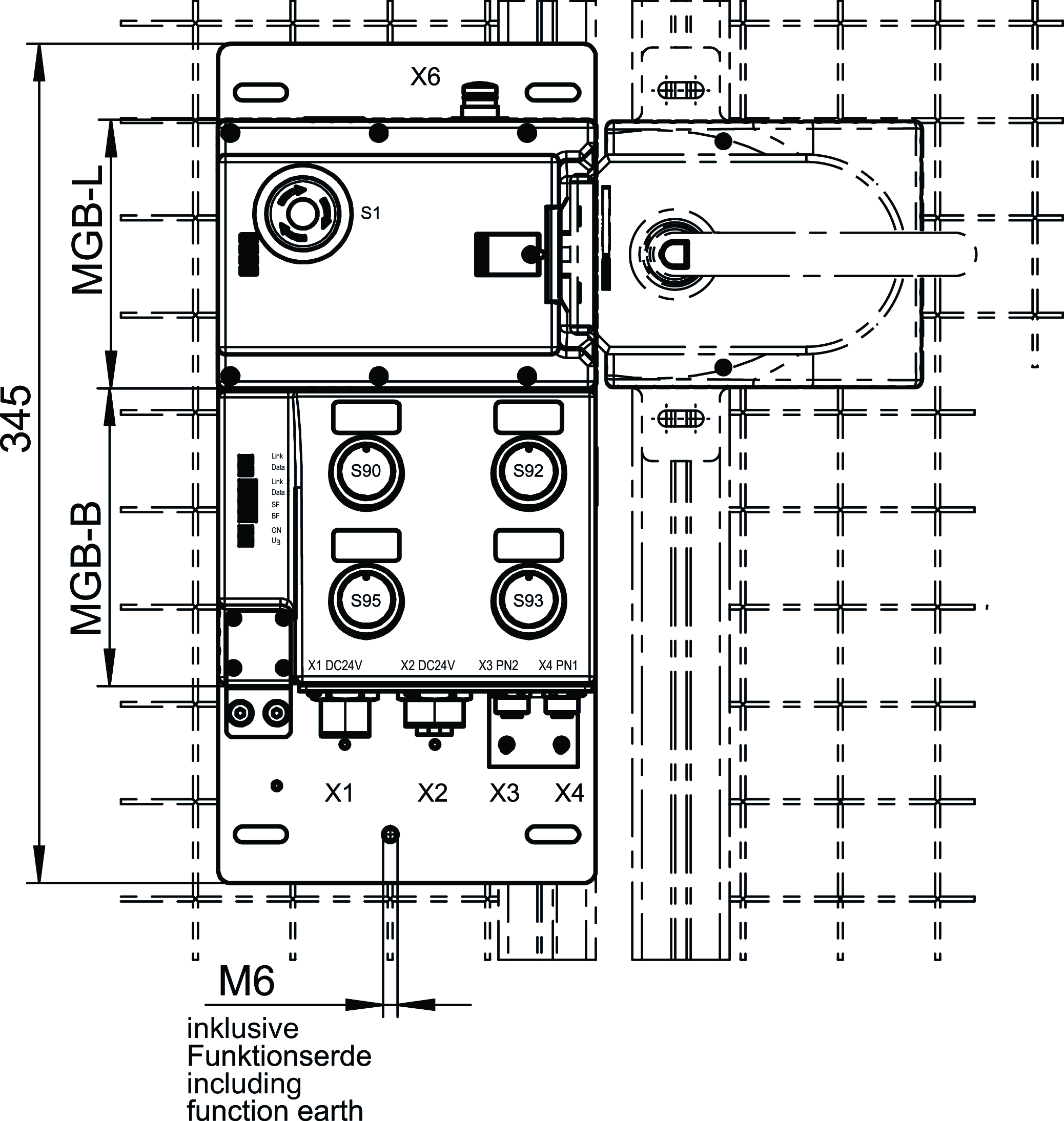
Dimensional drawings

Műszaki adatok
Approvals


Escape release MGB-E-A2-106051 (Order no. 106051)

Mechanical values and environment
| Installation orientation | any |
| Mechanical life | 1 x 10⁶ |
| Ambient temperature | -30 ... +55 °C |
| Material | |
| Housing | Die-cast zinc/stainless steel, powder-coated |
Miscellaneous
| Product version number | V2.0.0 |
| Additional feature | with mounting plate |
Handle modules MGB-H-AA1A2-L-106221 (Order no. 106221)

Mechanical values and environment
| Installation orientation | Door hinge DIN left |
| Degree of protection | IP65 |
| Ambient temperature | -20 ... +55 °C |
| Material | |
| Housing | Fiber glass reinforced plastic, nickel-plated die-cast zinc, stainless steel |
Miscellaneous
| Product version number | V3.0.0 |
| Additional feature | with mounting plate |
Locking modules MGB-L2B-EIA-L-136525 (Order no. 136525)

Workspace
| Secured switch-off distance sar | |
| Door position | max. 65 mm |
Operating and display elements
| Occupancy diagram | |
| L1 | |
| B1 |
| Item | Color | Extras | Switching element | Slide-in label | Note slide-in label | Version | Number | Designation1 | LED |
|---|---|---|---|---|---|---|---|---|---|
| 1 | with adhesive ring | 2 PD | Emergency stop illuminated | ||||||
| 90 | Red | 1NO | Illuminated pushbutton | ||||||
| 92 | Green | 1NO | Illuminated pushbutton | ||||||
| 93 | Yellow | 1NO | Illuminated pushbutton | ||||||
| 95 | Green | 1NO | Illuminated pushbutton |
Electrical connection values
| Connecting cable | |
| Ethernet | Ethernet/IP cable, at least cat. 5e |
| Rated insulation voltage Ui | 75 V |
| Rated impulse withstand voltage Uimp | 0.5 kV |
| EMC protection requirements | In accordance with EN 61000-4 and EN 61326-3-1 |
| maximum feed-in current in the connection block | |
| X1, X2 | max. 4000 mA |
| Safety class | III |
| Current consumption | max. 500 mA |
| Transponder coding | Unicode |
| Degree of contamination (external, according to EN 60947-1) | 3 |
| Power supply X1 | |
| Fuse | |
| external | min. 1 A slow blow |
| Operating voltage DC | |
| L1 | 24 V DC -15% ... +10% ((reverse polarity protected, regulated, residual ripple<5%, PELV)) |
| Auxiliary voltage DC | |
| L2 | 24 V DC -15% ... +10% (The auxiliary voltage is not required for the MGB system) |
| Power supply X2 | |
| Operating voltage DC | |
| L1 | 24 V DC -15% ... +10% (For looping through for connected devices) |
| Auxiliary voltage DC | |
| L2 | 24 V DC -15% ... +10% (For looping through for connected devices) |
Mechanical values and environment
| Connection type | |
| Ethernet/IP cable, at least cat. 5e | M12, D-coded, screened (X4) |
| 7/8" Power (X1) | |
| Plug connector M12 (X6) | |
| Ethernet/IP cable, at least cat. 5e | M12, D-coded, screened (X3) |
| 7/8" Power (X2) | |
| Installation orientation | Door hinge DIN left |
| Switching frequency | 0.25 Hz |
| Mechanical life | |
| 1 x 10⁶ | |
| in case of use as door stop, and 1 Joule impact energy | 0.1 x 10⁶ |
| Response time | |
| Door position | max. 250 ms Turn-off time (The reaction time is the max. time between the change in the input status and the deletion of the corresponding bit in the bus protocol.) |
| Emergency stop / machine stop | max. 100 ms Turn-off time (The reaction time is the max. time between the change in the input status and the deletion of the corresponding bit in the bus protocol.) |
| Bolt position | max. 250 ms Turn-off time (The reaction time is the max. time between the change in the input status and the deletion of the corresponding bit in the bus protocol.) |
| Guard locking | max. 250 ms Turn-off time (The reaction time is the max. time between the change in the input status and the deletion of the corresponding bit in the bus protocol.) |
| Shock and vibration resistance | Acc. to EN IEC 60947-5-3 |
| Degree of protection | IP54 |
| Ambient temperature | |
| with UB = 24 V DC | -20 ... +55 °C |
| Material | |
| Housing | Fiber glass reinforced plastic, nickel-plated die-cast zinc, stainless steel |
| Locking force FZh | 2000 N |
| Guard locking principle | Open-circuit current principle |
Characteristic values according to EN ISO 13849-1 and EN IEC 62061
| Mission time | 20 y |
| Safety Integrity Level | SIL 3 (EN 62061:2005) |
| Control of guard locking | |
| Category | 4 |
| Performance Level | PL e |
| PFHD | 4.91 x 10⁻⁹ (Fixed failure rate without consideration of faults in wearing parts.) |
| Emergency stop | |
| B10D | |
| Emergency stop | 0.13 x 10⁶ |
| Emergency-stop evaluation | |
| Category | 4 |
| Performance Level | PL e |
| PFHD | 3.05 x 10⁻⁹ (Fixed failure rate without consideration of faults in wearing parts.) |
| Monitoring of guard locking and the guard position | |
| Diagnostic Coverage (DC) | 99 % |
| Category | 4 |
| Performance Level | PL e |
| PFHD | 3.37 x 10⁻⁹ (Fixed failure rate without consideration of faults in wearing parts.) |
Miscellaneous
| Slide-in label | |||||||
| |||||||
| Product version number | V1.5 | ||||||
Interface
| Bus data protocol | Ethernet/IP |
| Safety data protocol | CIP Safety |
| Date interface | |
| Ethernet |
Komponensek

MGB-E-A2-106051
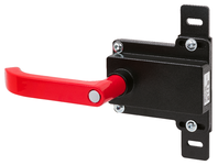
Escape release module MGB-E... pre-assembled on mounting plate
- Escape release from the danger zone
- Mounted on mounting plate
- Signal red door handle
- Designed for door profiles up to 40 mm
- Extended actuation axis for thicker doors (available optionally)
MGB-H-AA1A2-L-106221
Handle module MGB-H-...
- Intelligent bolt tongue
- Lockout mechanism
- Door handle
- Mounting plate
MGB-L2B-EIA-L-136525
Locking module MGB-L2...-EI (guard locking by solenoid force) with 4 pushbuttons, emergency stop, 7/8" and M12 plugs
- Guard locking with guard lock monitoring
- Emergency stop according to ISO 13850, illuminated
- 4 illuminated pushbuttons
- including adhesive labels
- Connection via 7/8" and M12 plugs
- including terminal plug for stack light (M12, 5-pin)
- Pre-assembled on mounting plates
- Unicode
Tartozékok
Letöltések
Teljes csomag
Minden fontos dokumentum letöltése egyetlen kattintással.
Tartalom:
- A használati utasítás és a használati utasítás vagy a rövid utasítás kiegészítései
- A használati utasítást kiegészítő adatlapok
- A megfelelőségi nyilatkozat
Egyedi dokumentumok


Egyéb dokumentumok
CAD-adatok
Rendelési adatok
| Rend. sz. | 161480 |
| Cikk neve | MGB-L2HEB-EIA-L-161480 |
| Súly | 6,96kg |
| Vámtarifaszám | 85371098 |
| ECLASS | 27-27-24-05 Safety-related transponder switch with guardlocking |


