MGB-L1CB-PNA-L-124820 (Sip. No. 124820)
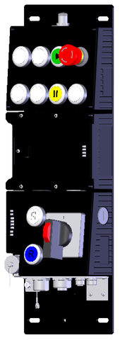
Evaluation module with control and bus module MGB-...-PN with 11 controls and indicators, 7/8" and M12 plugs, RC12
- Guard locking with guard lock monitoring
- Emergency stop according to ISO 13850, illuminated
- 9 illuminated pushbuttons
- Operating mode selector
- Connection via 7/8" and M12 plugs
- including terminal plug for stack light (M12, 5-pin)
- including terminal plug for enabling switch (RC12, 12-pin)
- Pre-assembled on mounting plates
- Integrated Profinet RT switch
- Unicode

Açıklama
Profinet connection
7/8" plugs according to ANSI/B93.55M-1981 and M12 plugs (d-coded) according to IEC 61076-2-101
Profinet RT switch
Point-to-point topology network structure due to integrated RT switch.
Flexible use as interlocking or guard locking
By means of the corresponding evaluation of the safe device data by the control system, use can be as either interlocking or guard locking (with or without monitoring).
Illuminated emergency stop
Emergency stop with illumination that can be controlled as required.

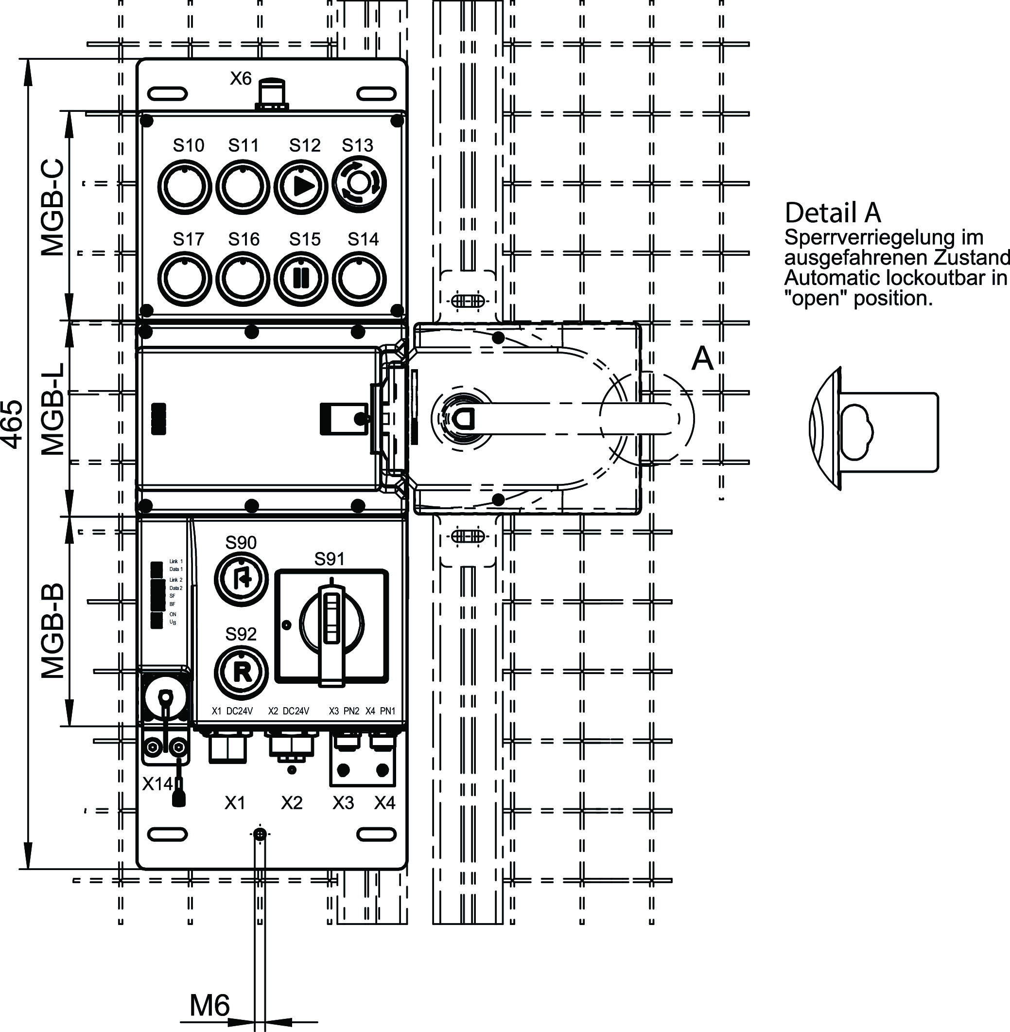
Dimensional drawings

Teknik Veriler
Approvals


Workspace
| Rated operating distances Sn | 20 mm (Only applies for use on sliding doors with deactivated guard lock monitoring) |
Operating and display elements
| Occupancy diagram | |
| C1 | |
| L0 | |
| B2 |
| Item | Color | Extras | Version | Slide-in label | Note slide-in label | Switching element | Number | Designation1 | LED |
|---|---|---|---|---|---|---|---|---|---|
| 10 | white | Illuminated pushbutton | 1NO | ||||||
| 11 | white | Illuminated pushbutton | 1NO | ||||||
| 12 | Green | printed | Illuminated pushbutton | 1NO | |||||
| 13 | Emergency stop illuminated | 2 PD | |||||||
| 14 | white | Illuminated pushbutton | 1NO | ||||||
| 15 | Yellow | printed | Illuminated pushbutton | 1NO | |||||
| 16 | white | Illuminated pushbutton | 1NO | ||||||
| 17 | white | Illuminated pushbutton | 1NO | ||||||
| 90 | white | printed | Illuminated pushbutton | 1NO | |||||
| 91 | Operating mode selector | O ; I | Code 2 of 3 | ||||||
| 92 | Blue | printed | Illuminated pushbutton | 1NO |
Electrical connection values
| Connecting cable | |
| Ethernet | Profinet I/O cable, at least cat. 5e |
| Rated insulation voltage Ui | 75 V |
| Rated impulse voltage Uimp | 0.5 kV |
| EMC protection requirements | In accordance with EN 61000-4 and EN 61326-3-1 |
| maximum feed-in current in the connection block | |
| X1, X2 | max. 4000 mA |
| Safety class | III |
| Current consumption | max. 500 mA |
| Transponder coding | Unicode |
| Degree of contamination (external, according to EN 60947-1) | 3 |
| Power supply X1 | |
| Fuse | |
| external | min. 1 A slow blow |
| Operating voltage DC | |
| L1 | 24 V DC -15% ... +10% ((reverse polarity protected, regulated, residual ripple<5%, PELV)) |
| Auxiliary voltage DC | |
| L2 | 24 V DC -15% ... +10% (The auxiliary voltage is not required for the MGB system) |
| Power supply X2 | |
| Operating voltage DC | |
| L1 | 24 V DC -15% ... +10% (For looping through for connected devices) |
| Auxiliary voltage DC | |
| L2 | 24 V DC -15% ... +10% (For looping through for connected devices) |
Mechanical values and environment
| Connection type | |
| for Stacklight | Plug connector M12 (X6) |
| according to IEC 61076-2-101, Profinet I/O cable, at least cat. 5e | M12, D-coded, screened (X3 (The PROFINET 'Cabling and Interconnection Technology' document from the PNO helps with the correct selection of cables).) |
| for enabling switch | Plug connector RC12 (X14) |
| according to IEC 61076-2-101, Profinet I/O cable, at least cat. 5e | M12, D-coded, screened (X4 (The PROFINET 'Cabling and Interconnection Technology' document from the PNO helps with the correct selection of cables).) |
| 7/8" Power (X2 (The PROFINET 'Cabling and Interconnection Technology' document from the PNO helps with the correct selection of cables).) | |
| 7/8" Power (X1 (The PROFINET 'Cabling and Interconnection Technology' document from the PNO helps with the correct selection of cables).) | |
| Installation orientation | Door hinge DIN left |
| Switching frequency | 0.25 Hz |
| Mechanical life | |
| 1 x 10⁶ | |
| in case of use as door stop, and 1 Joule impact energy | 0.1 x 10⁶ |
| Response time | |
| Bolt position | max. 550 ms Turn-off time (The reaction time is the max. time between the change in the input status and the deletion of the corresponding bit in the bus protocol.) |
| Emergency stop / machine stop | max. 250 ms Turn-off time (The reaction time is the max. time between the change in the input status and the deletion of the corresponding bit in the bus protocol.) |
| Operating mode selector | max. 220 ms Turn-off time (The reaction time is the max. time between the change in the input status and the deletion of the corresponding bit in the bus protocol.) |
| Door position | max. 550 ms Turn-off time (The reaction time is the max. time between the change in the input status and the deletion of the corresponding bit in the bus protocol.) |
| Guard locking | max. 550 ms Turn-off time (The reaction time is the max. time between the change in the input status and the deletion of the corresponding bit in the bus protocol.) |
| Enabling switch | max. 250 ms Turn-off time (The reaction time is the max. time between the change in the input status and the deletion of the corresponding bit in the bus protocol.) |
| Shock and vibration resistance | Acc. to EN IEC 60947-5-3 |
| Degree of protection | IP54 |
| Ambient temperature | |
| with UB = 24 V DC | -20 ... +55 °C |
| Material | |
| Housing | Fiber glass reinforced plastic, nickel-plated die-cast zinc, stainless steel |
| Locking force FZh | 2000 N |
| Guard locking principle | Closed-circuit current principle |
Characteristic values according to EN ISO 13849-1 and EN IEC 62061
| PL | Maximum SIL | PFHD | Category | Mission time | |
|---|---|---|---|---|---|
| Control of guard locking | PL e | - | 3.91x10⁻⁸ | 4 | 20 y |
| Monitoring of the guard position | PL e | 3 | 4.07x10⁻⁸ | 4 | 20 y |
| Monitoring of guard locking | PL e | 3 | 4.07x10⁻⁸ | 4 | 20 y |
| Safe multi-position switch | PL e | 3 | 4.1x10⁻⁸ | 4 | 20 y |
| Evaluating safety signals | PL e | 3 | 4.1x10⁻⁸ | 4 | 20 y |
| Applies to all additionally included safety functions such as EMERGENCY STOP, enabling switch, etc. | |||||
| B10D | Mission time | |
|---|---|---|
| Emergency stop | 0.13x10⁶ | 20 y |
Miscellaneous
| Product version number | V3.30.10 |
Interface
| Bus data protocol | Profinet (IEC 61158 type 10) |
| Safety data protocol | Profisafe (IEC 61784-3-3) |
| Date interface | |
| Ethernet |
Aksesuar
ZSA092141C2038
- Housing G1
- 3-stage function
- Straight connecting cable with plug connector, 5 m
- Direct connection to safety switch
ZSA097567C2038
- Housing G1
- 3-stage function
- Straight connecting cable with plug connector, 10 m
- Direct connection to safety switch
ZSA099495C2038
- Housing G1
- 3-stage function
- Straight connecting cable with plug connector, 15 m
- Direct connection to safety switch
ZSA100873C2038
- Housing G1
- 3-stage function
- Straight connecting cable with plug connector, 25 m
- Direct connection to safety switch
İndirme
Komple paket
Tüm önemli belgeleri tek bir tıklama ile indirin.
İçerik:
- Kullanım talimatları ve kullanım talimatlarına veya kısa talimatlara yapılan tüm eklemeler
- Kullanım talimatlarını tamamlayan tüm veri sayfaları
- Uygunluk beyanı
Tek Belgeler


Diğer Belgeler


Sipariş verileri
| Sip. No. | 124820 |
| Makale adı | MGB-L1CB-PNA-L-124820 |
| Ağırlık | 4,602kg |
| Gümrük sınıfı | 85371098 |
| ECLASS | 27-27-24-05 Safety-related transponder switch with guardlocking |


