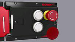
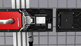
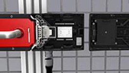
Locking set MGB-L2...-EI (guard locking by solenoid force) with 3 pushbuttons, emergency stop, RC12
- Guard locking with guard lock monitoring
- Emergency stop according to ISO 13850, illuminated
- 3 illuminated pushbuttons
- Connection via M12 plug
- including terminal plug for enabling switch
- Pre-assembled on mounting plates
- Unicode
Açıklama
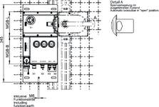
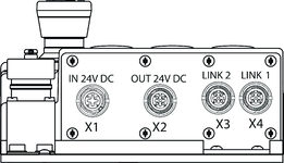
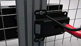
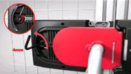
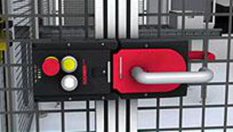
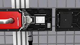
Dimensional drawings
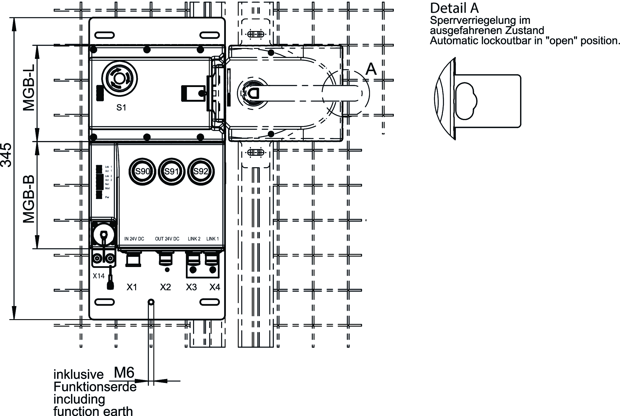
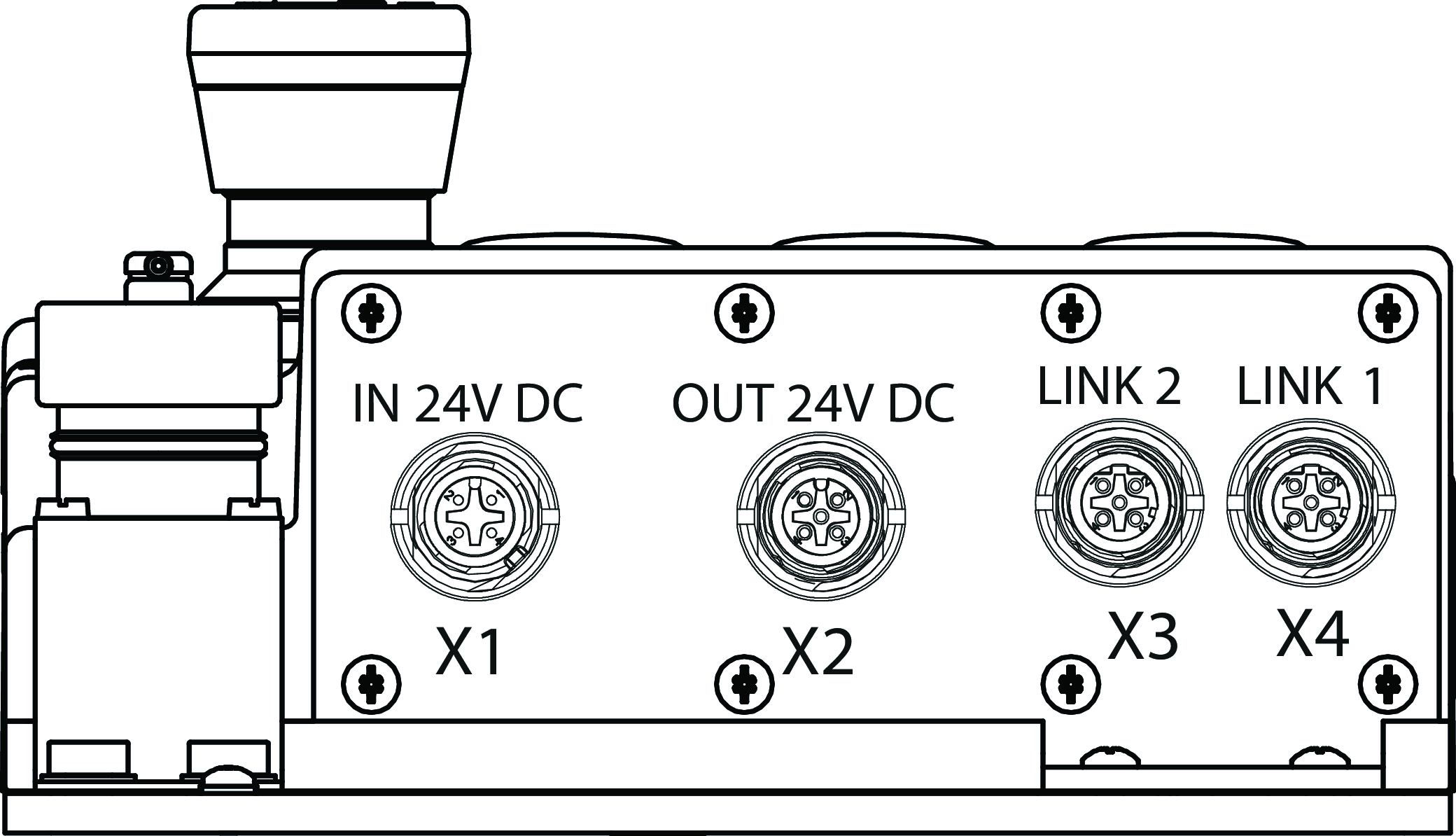
Connection examples
Teknik Veriler
Approvals


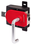
Handle modules MGB-H-AA1A6-L-111839 (Order no. 111839)
Mechanical values and environment
| Installation orientation | Door hinge DIN left |
| Degree of protection | IP65 |
| Ambient temperature | -20 ... +55 °C |
| Material | |
| Housing | Fiber glass reinforced plastic, nickel-plated die-cast zinc, stainless steel |
Miscellaneous
| Product version number | V3.0.0 |
| Additional feature | with mounting plate and automatic lockout mechanism |
Locking modules MGB-L2B-EIA-L-136522 (Order no. 136522)

Workspace
| Secured switch-off distance sar | |
| Door position | max. 65 mm |
Operating and display elements
| Occupancy diagram | |
| B1 | |
| L1 |
| Item | Color | Extras | Switching element | Slide-in label | Note slide-in label | Version | Number | Designation1 | LED |
|---|---|---|---|---|---|---|---|---|---|
| 1 | with adhesive ring | 2 PD | Emergency stop illuminated | ||||||
| 90 | 1NO | Illuminated pushbutton | |||||||
| 91 | 1NO | Illuminated pushbutton | |||||||
| 92 | 1NO | Illuminated pushbutton |
Electrical connection values
| Connecting cable | |
| Ethernet | Ethernet/IP cable, at least cat. 5e |
| Rated insulation voltage Ui | 75 V |
| Rated impulse withstand voltage Uimp | 0.5 kV |
| EMC protection requirements | In accordance with EN 61000-4 and EN 61326-3-1 |
| maximum feed-in current in the connection block | |
| X1, X2 | max. 4000 mA |
| Safety class | III |
| Current consumption | max. 500 mA |
| Transponder coding | Unicode |
| Degree of contamination (external, according to EN 60947-1) | 3 |
| Power supply X1 | |
| Fuse | |
| external | min. 1 A slow blow |
| Operating voltage DC | |
| L1 | 24 V DC -15% ... +10% ((reverse polarity protected, regulated, residual ripple<5%, PELV)) |
| Auxiliary voltage DC | |
| L2 | 24 V DC -15% ... +10% (The auxiliary voltage is not required for the MGB system) |
| Power supply X2 | |
| Operating voltage DC | |
| L1 | 24 V DC -15% ... +10% (For looping through for connected devices) |
| Auxiliary voltage DC | |
| L2 | 24 V DC -15% ... +10% (For looping through for connected devices) |
Mechanical values and environment
| Connection type | |
| Plug connector RC12 (X14) | |
| Ethernet/IP cable, at least cat. 5e | M12, D-coded, screened (X3) |
| M12 Power, A-coded (X1) | |
| M12 Power, A-coded (X2) | |
| Ethernet/IP cable, at least cat. 5e | M12, D-coded, screened (X4) |
| Installation orientation | Door hinge DIN left |
| Switching frequency | 0.25 Hz |
| Mechanical life | |
| in case of use as door stop, and 1 Joule impact energy | 0.1 x 10⁶ |
| 1 x 10⁶ | |
| Response time | |
| Guard locking | max. 250 ms Turn-off time (The reaction time is the max. time between the change in the input status and the deletion of the corresponding bit in the bus protocol.) |
| Enabling switch | max. 100 ms Turn-off time (The reaction time is the max. time between the change in the input status and the deletion of the corresponding bit in the bus protocol.) |
| Door position | max. 250 ms Turn-off time (The reaction time is the max. time between the change in the input status and the deletion of the corresponding bit in the bus protocol.) |
| Bolt position | max. 250 ms Turn-off time (The reaction time is the max. time between the change in the input status and the deletion of the corresponding bit in the bus protocol.) |
| Emergency stop | max. 100 ms Turn-off time (The reaction time is the max. time between the change in the input status and the deletion of the corresponding bit in the bus protocol.) |
| Shock and vibration resistance | Acc. to EN IEC 60947-5-3 |
| Degree of protection | IP54 |
| Ambient temperature | |
| with UB = 24 V DC | -20 ... +55 °C |
| Material | |
| Housing | Fiber glass reinforced plastic, nickel-plated die-cast zinc, stainless steel |
| Locking force FZh | 2000 N |
| Guard locking principle | Open-circuit current principle |
Characteristic values according to EN ISO 13849-1 and EN IEC 62061
| Mission time | 20 y |
| Safety Integrity Level | SIL 3 (EN 62061:2005) |
| Control of guard locking | |
| Category | 4 |
| Performance Level | PL e |
| PFHD | 4.91 x 10⁻⁹ (Fixed failure rate without consideration of faults in wearing parts.) |
| Emergency stop | |
| B10D | |
| Emergency stop | 0.13 x 10⁶ |
| Enabling switch | |
| B10D | |
| Enabling switch | (Acc. to manufacturer’s specifications) |
| Emergency-stop evaluation | |
| Category | 4 |
| Performance Level | PL e |
| PFHD | 3.05 x 10⁻⁹ (Fixed failure rate without consideration of faults in wearing parts.) |
| Enabling switch evaluation | |
| Category | 4 |
| Performance Level | PL e |
| PFHD | 5.03 x 10⁻¹² (Fixed failure rate without consideration of faults in wearing parts.) |
| Monitoring of guard locking and the guard position | |
| Diagnostic Coverage (DC) | 99 % |
| Category | 4 |
| Performance Level | PL e |
| PFHD | 3.37 x 10⁻⁹ (Fixed failure rate without consideration of faults in wearing parts.) |
Miscellaneous
| Product version number | V1.5 |
| Additional feature | incl. lens set, ID no. 120344 |
Interface
| Bus data protocol | Ethernet/IP |
| Safety data protocol | CIP Safety |
| Date interface | |
| Ethernet |
Bileşenler

111839
MGB-H-AA1A6-L-111839
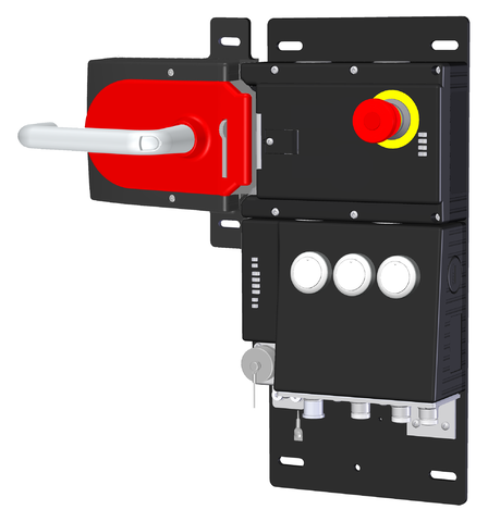
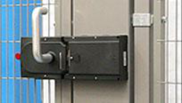
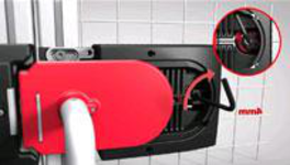
Handle module MGB-H... with automatically extending lockout mechanism
MGB-H-AA1A6-L-111839
Handle module MGB-H... with automatically extending lockout mechanism
- Intelligent bolt tongue
- Fold-out lockout mechanism
- Second automatically extending lockout mechanism
- Door handle
- Mounting plate
136522
MGB-L2B-EIA-L-136522
Locking module MGB-L2...-EI (guard locking by solenoid force) with 3 pushbuttons, emergency stop, RC12
MGB-L2B-EIA-L-136522
Locking module MGB-L2...-EI (guard locking by solenoid force) with 3 pushbuttons, emergency stop, RC12
- Guard locking with guard lock monitoring
- Emergency stop according to ISO 13850, illuminated
- 3 illuminated pushbuttons
- Connection via M12 plug
- including terminal plug for enabling switch
- Pre-assembled on mounting plates
- Unicode
Aksesuar
Function expansion
MGB-EI
ZSA
ZSA, 3-stage, with cable and plug connector RC12


092141
ZSA092141C2038
ZSA092141C2038
- Housing G1
- 3-stage function
- Straight connecting cable with plug connector, 5 m
- Direct connection to safety switch
097567
ZSA097567C2038
ZSA097567C2038
- Housing G1
- 3-stage function
- Straight connecting cable with plug connector, 10 m
- Direct connection to safety switch
099495
ZSA099495C2038
ZSA099495C2038
- Housing G1
- 3-stage function
- Straight connecting cable with plug connector, 15 m
- Direct connection to safety switch
100873
ZSA100873C2038
ZSA100873C2038
- Housing G1
- 3-stage function
- Straight connecting cable with plug connector, 25 m
- Direct connection to safety switch
İndirme
Komple paket
Tüm önemli belgeleri tek bir tıklama ile indirin.
İçerik:
- Kullanım talimatları ve kullanım talimatlarına veya kısa talimatlara yapılan tüm eklemeler
- Kullanım talimatlarını tamamlayan tüm veri sayfaları
- Uygunluk beyanı
Tek Belgeler
Declarations of conformity
EU-Konformitätserklärung

Dok. No.
Versiyon
Dil
Boyut

EU-Konformitätserklärung
Dok. No.
EDC2123624
Versiyon
Dil
Boyut
0,2 MB
UKCA-Konformitätserklärung

Dok. No.
Versiyon
Dil
Boyut

UKCA-Konformitätserklärung
Dok. No.
EDC20001506
Versiyon
Dil
Boyut
0,1 MB
Instructions
Operating Instructions Safety Systems MGB-L..B-EI-… (Ethernet/IP) and With Data Structure Type A From V1.5.0


Dok. No.
Versiyon
Dil
Boyut

Operating Instructions Safety Systems MGB-L..B-EI-… (Ethernet/IP) and With Data Structure Type A From V1.5.0
Dok. No.
2126330
Versiyon
09/21
Dil
Boyut
2,9 MB

Manual de instrucciones Sistemas de seguridad MGB-L..B-EI-… (Ethernet/IP) y con estructura de datos de tipo A V1.5.0 o superior
Dok. No.
2126330
Versiyon
09/21
Dil
Boyut
3,0 MB

Betriebsanleitung Sicherheitssysteme MGB-L..B-EI-… (Ethernet/IP) und mit Datenstruktur Typ A ab V1.5.0
Dok. No.
2126330
Versiyon
09/21
Dil
Boyut
2,9 MB

사용 설명서 안전 시스템 MGB-L..B-EI-…(이더넷/IP) 데이터 구조 타입 A 포함 V1.5.0부터
Dok. No.
2126330
Versiyon
09/21
Dil
Boyut
3,3 MB

Instrucțiuni de utilizare Sisteme de siguranță MGB-L..B-EI-… (Ethernet/IP) și cu structură de date tip A începând de la versiunea V1.5.0
Dok. No.
2126330
Versiyon
09/21
Dil
Boyut
3,1 MB
Diğer Belgeler
CAD Verileri
Sipariş verileri
| Sip. No. | 157791 |
| Makale adı | MGB-L2HB-EIA-L-157791 |
| Ağırlık | 5,86kg |
| Gümrük sınıfı | 85371098 |
| ECLASS | 27-27-24-05 Safety-related transponder switch with guardlocking |


