Non-contact safety switches CES-I-BR-CC-FLX-C07, with FlexFunction, suitable for actuators with same coding
- Safety switch with integrated evaluation electronics
- Suitable for actuator with same coding
- Several devices can be connected in series, max. 20
- Switch chains up to 200 m long
- 2 safety outputs (semiconductor outputs)
- Short circuit monitoring
- Diagnostic information via BR IO-Link Gateway
- Category 4 / PL e according to EN ISO 13849-1
- Three active faces
- Plug connector M12, 8-pin (aligned)
- The safety switch can be used only in conjunction with actuators designated for this purpose.
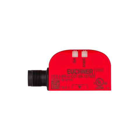
Açıklama
Industry 4.0 ready
The switch can communicate in combination with an EUCHNER BR IO-Link Gateway, and sends process and device data to higher-level control systems. Comprehensive diagnostic messages enable rapid and targeted troubleshooting.
Highly coded evaluation
The actuators of a packaging unit must be assigned to the safety switch by a teach-in operation so that they are detected by the system. This unambiguous assignment ensures a particularly high level of protection against tampering. The system thus possesses a high coding level.
The coding is identical for all the actuators in a packaging unit. Actuators from different packaging units are coded differently. Only one actuator from a packaging unit has to be taught-in. All other actuators from the same package can be used without an additional teach-in operation.
The switch detects only taught-in actuators. When an actuator from a new packaging unit is taught-in, the code for actuators from the previous packaging unit is disabled.
Category according to EN 13849-1
Due to two redundantly designed semiconductor outputs (safety outputs) with internal monitoring suitable for:
- Category 4/PL e according to EN 13849-1
Important: To achieve the stated category according to EN ISO 13849-1, both safety outputs (FO1A and FO1B) must be evaluated.
LED indicator
STATE | Status LED |
DIA | Diagnostics LED |
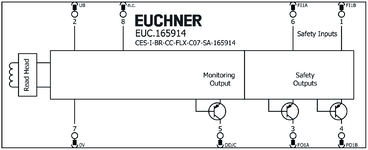
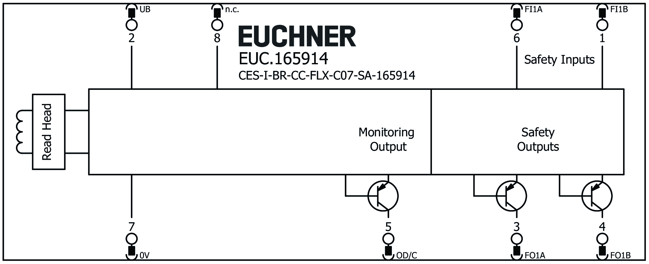
Terminal assignment
| Pin | Designation | Function |
|---|---|---|
| 1 | FI1B | Enable input for channel B |
| 2 | UB | Power supply, DC 24 V |
| 3 | FO1A | Safety output, channel A |
| 4 | FO1B | Safety output, channel B |
| 5 | OD/C | Monitoring output/communication |
| 6 | FI1A | Enable input for channel A |
| 7 | 0 V | Ground, DC 0 V |
| 8 | nc | n.c. |
Notice
The caps for the mounting holes are included.
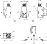
Dimensional drawings
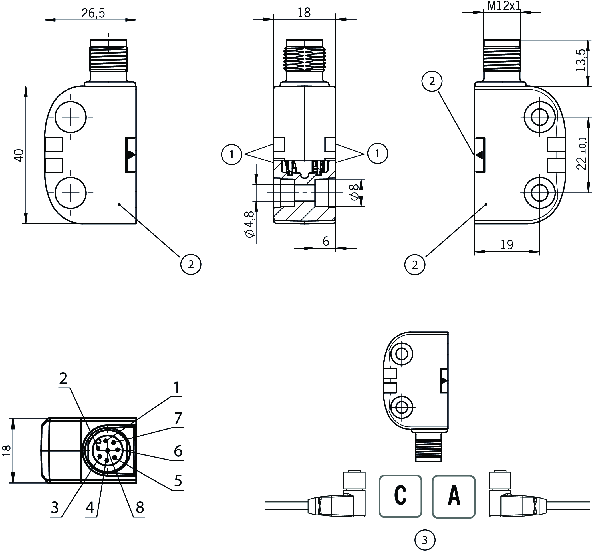
| 1 | LEDs |
| 2 | Active face |
| 3 | With the installation orientation shown: cable outlet on left or right |
Connection examples
Teknik Veriler
Approvals


Workspace
| Repeat accuracy R | |
| according to EN 60947-5-2 | <= 10 |
Electrical connection values
| Fuse | |
| external (operating voltage) | 0.25 ... 8 A |
| rated conditional short-circuit current | 100 A |
| Rated insulation voltage Ui | 75 V |
| Rated impulse voltage Uimp | 1.5 kV |
| Operating voltage DC | |
| UB | 24 V DC -15% ... +15% regulated, residual ripple<5%, PELV |
| Turn-on time | |
| Safety outputs | max. 100 ms |
| EMC protection requirements | Acc. to EN IEC 60947-5-3 |
| Risk time according to EN 60947-5-3 | max. 125 ms |
| Risk time according to EN 60947-5-3, extension for each additional device | max. 10 ms |
| Safety class | III |
| Current consumption | 40 mA |
| Degree of contamination (external, according to EN 60947-1) | 3 |
| Monitoring output OD/C | |
| Output type | p-switching, short circuit-proof |
| Output voltage | UB-1.5 ... UB V DC |
| Switching current | 1 ... 50 mA |
| Safety outputs FO1A / FO1B | |
| Output type | Semiconductor outputs, p-switching, short circuit-proof |
| Output voltage | |
| HIGH U(FO1A) / U(FO1B) | UB-1.5V ... UB V DC (Values at a switching current of 50 mA without taking into account the cable lengths.) |
| LOW U(FO1A) / U(FO1B) | 0 ... 1 V DC |
| Discrepancy time | max. 10 ms |
| Utilization category | |
| DC-13 | 24 V 150 mA (Caution: outputs must be protected with a free-wheeling diode in case of inductive loads.) |
| Off-state current Ir | max. 0.25 mA |
| Switching current | 1 ... 150 mA |
| Test pulse duration | 0.3 ms (Applies to a load with C<= 30 nF and R<= 20 kohm) |
| Test pulse interval | ca 100 ms |
Mechanical values and environment
| Dimensions | 40 x 26.5 x 18 |
| Connection type | M12 plug connector, 8-pin |
| Tightening torque | max. 0.8 Nm |
| Ready delay | 5 s |
| Operating altitude | max. 4 000 m |
| Installation orientation | any |
| Switching frequency | max. 1 Hz |
| Mounting distance | |
| between switches | min. 50 mm |
| Mounting type | non-flush on metal |
| Shock and vibration resistance | Acc. to EN IEC 60947-5-3 |
| Degree of protection | IP65/IP67/IP69/IP69K |
| Ambient temperature | |
| with UB = 24 V DC | -25 ... +55 °C (+65 °C at IL= max. 10 mA per safety output) |
| Material | |
| Housing | Plastic, PBT-PC-GF30 |
Characteristic values according to EN ISO 13849-1 and EN IEC 62061
| Mission time | |
| according to EN ISO 13849-1 | |
| SIL CL | |
| according to EN 62061:2005/A2:2015 |
Characteristic values according to EN ISO 13849-1 and EN IEC 62061
| PL | Maximum SIL | PFHD | Category | Mission time | |
|---|---|---|---|---|---|
| Monitoring of the guard position | PL e | 3 | 6x10⁻¹⁰ | 4 | 20 y |
Miscellaneous
| Notices for UL approval | Operation only with UL Class 2 power supply or equivalent measures |
| Additional feature | Caps included |
In combination with actuator S-C07-04-V02-165928
| Switch-on distance | |
| Installation position C + D | 7 mm |
| Installation position A + B | 13 mm |
| Secured switch-off distance sar | |
| in x direction/installation position A + B | max. 20 mm |
| in x direction/installation position C + D | max. 17 mm |
| Secured switching distance sao | |
| in x direction/installation position B | min. 9 mm |
| in x direction/installation position A | min. 10 mm |
| in x direction/installation position C | min. 3 mm |
| in x direction/installation position D | min. 2 mm |
| Switching hysteresis | 1 ... 2 mm |
Aksesuar

AC-YD-V0,2-SBB-158192
- For series connection of BR safety switches in switch chains with IO-Link evaluation
- Y-distributor with M12 female plug, 8-pin
- Male plug straight, 5-pin
- Female plug straight, 5-pin
- TPU housing, black
- Cable length 0.2 m / PVC

AC-YD-V1,0-SBB-158193
- For series connection of AR/BR safety switches in switch chains with ESM-CB for IO-Link evaluation
- Y-distributor with M12 female plug, 8-pin
- Male plug straight, 5-pin
- Female plug straight, 5-pin
- TPU housing, black
- Cable length 1.0 m

AC-YD-V0,2-SBB-111696
- For series connection of AR/BR safety switches in switch chains without IO-Link evaluation
- Y-distributor M12 with connecting cable, 2 x 5-pin, 1 x 8-pin
- Straight plug connector
- PVC cable
- Cable length 0.2 m

AC-YD-V1,0-SBB-112395
- For series connection of AR/BR safety switches in switch chains without IO-Link evaluation
- Y-distributor M12 with connecting cable, 2 x 5-pin, 1 x 8-pin
- Straight plug connector
- PVC cable
- Cable length 1 m
İndirme
Komple paket
Tüm önemli belgeleri tek bir tıklama ile indirin.
İçerik:
- Kullanım talimatları ve kullanım talimatlarına veya kısa talimatlara yapılan tüm eklemeler
- Kullanım talimatlarını tamamlayan tüm veri sayfaları
- Uygunluk beyanı
Tek Belgeler


Diğer Belgeler


CAD Verileri
Sipariş verileri
| Sip. No. | 165914 |
| Makale adı | CES-I-BR-CC-FLX-C07-SA-165914 |
| Ağırlık | 0,061kg |
| Gümrük sınıfı | 85365019 |
| ECLASS | 27-27-24-03 Safety-related transponder switch |


