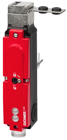
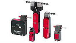
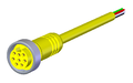
STA3A-2131A024L024BHA10C2398 (Sip. No. 119366)
STA safety switch, BHA plug connector(s) (MR10), contacts for door position, escape release
- Plug connector(s) BHA (MR10)
- Contacts for the door position
- Auxiliary release
- Escape release, long
- LED indicator
- Closed-circuit current principle
Açıklama
Approach direction

Horizontal and vertical
Can be adjusted in 90° steps
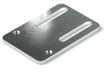
Increased overtravel with horizontal approach direction
If increased play is required when the door is closed, an actuator with overtravel is available. This actuator allows the door to move slightly in the actuating direction when closed. This is important, for example, if safety doors have a rubber buffer as an end stop. An actuator with overtravel can reduce the permanent pressure of the compressed rubber buffer. This reduces the load on both the switch head and the door mechanism.
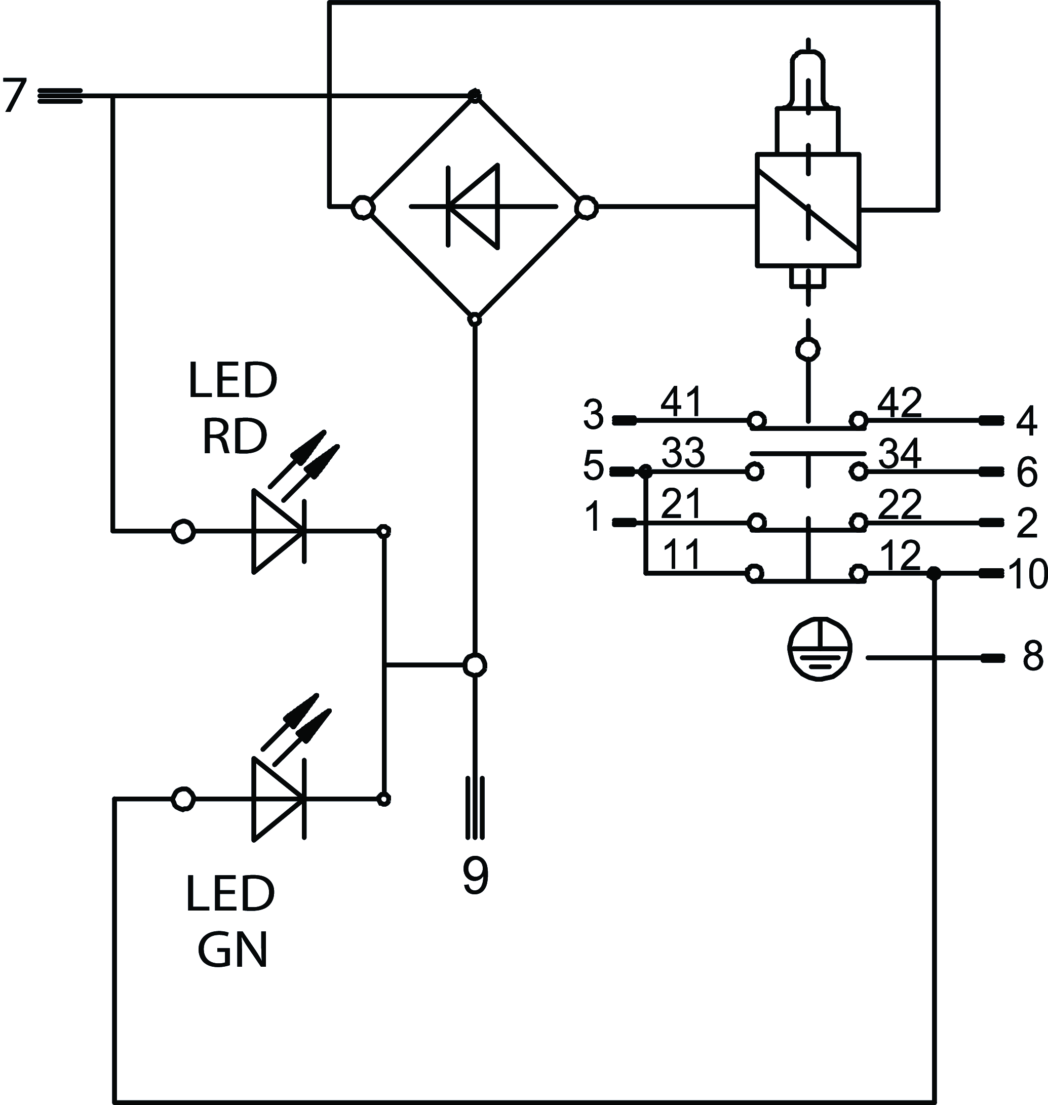
LED indicator
The switch has two freely assignable LED indicators (red and green).
Guard locking principle
closed-circuit current (power to unlock): In a safety guard with guard locking according to the closed-circuit current principle, the guard is locked by spring force until the guard locking solenoid is supplied with current. The guard is unlocked by means of magnetic force. This is also referred to as mechanical guard locking.
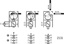
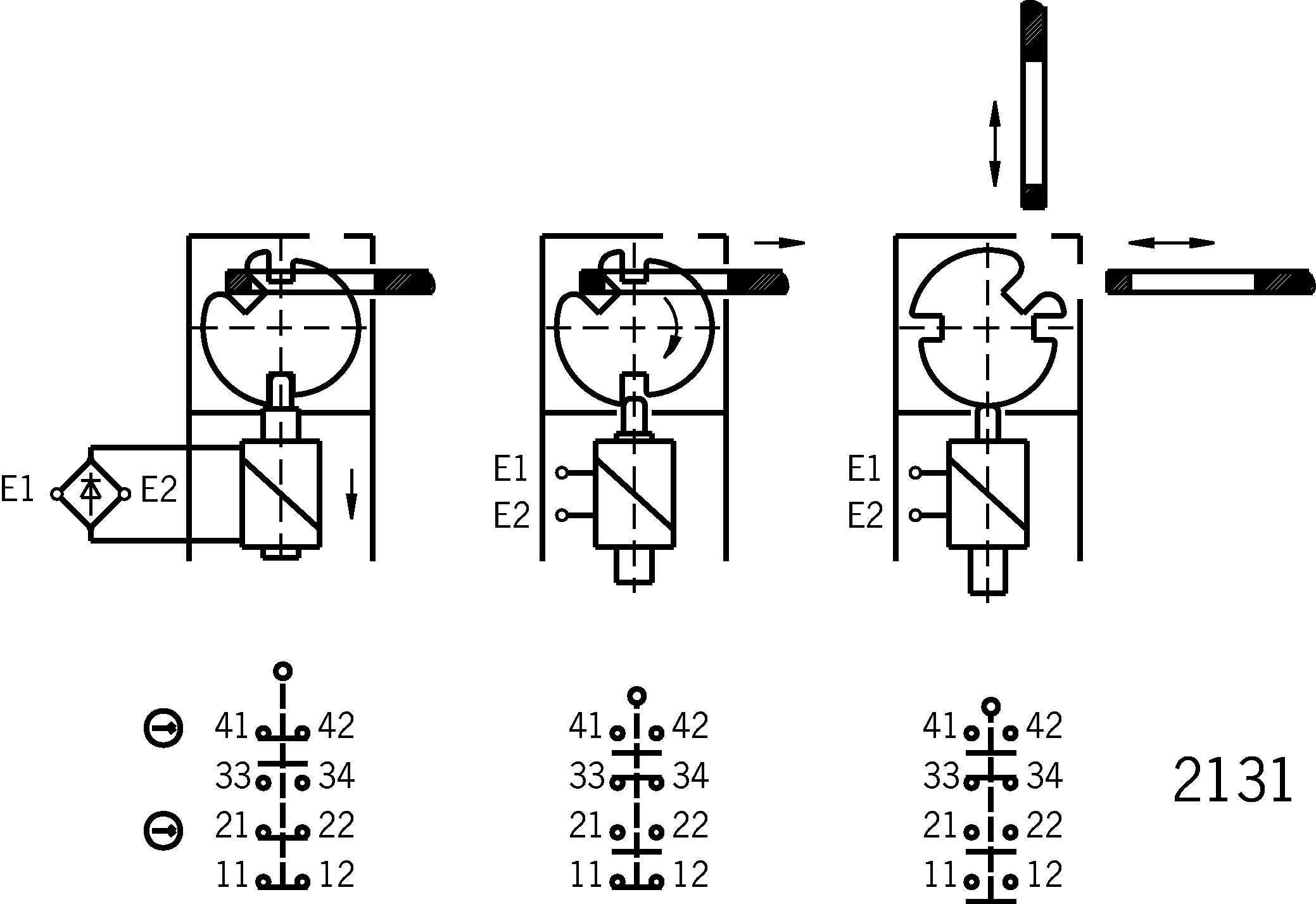
Switching element
2131 | Slow-action switching contact |
Contacts for guard locking: 2 positively driven, positively driven contacts | |
Contacts for door monitoring: 1 NC contact |
 1 NO contact
Auxiliary release
The auxiliary release on the front allows access to the machine in the event of a malfunction, e.g. a power failure. It is unlocked using a tool or a key. The auxiliary release must be secured against misuse (sealing, laking).
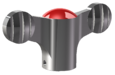
Escape release
This is used for manual release of guard locking from the danger zone without tools.
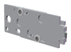
Required accessories
Actuator is not included in the scope of delivery.
Functional drawings
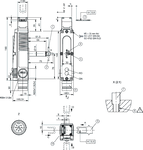
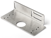
Dimensional drawings
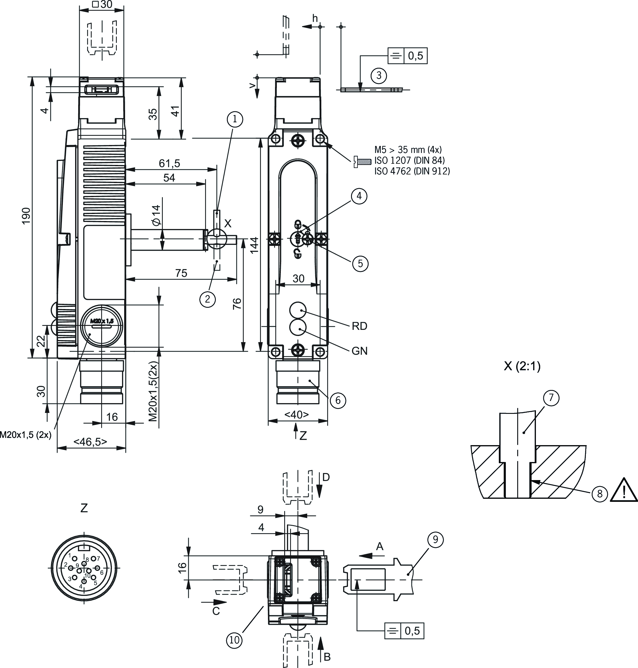
| 1 | Escape release, basic position |
| 10 | Actuating direction: After the fixing screws are unscrewed, the actuating head can be changed to the required approach direction. |
| 2 | Escape release, unlocked position |
| 3 | Safety switch and actuator must be placed together for mounting on the machine. Do not use actuating head as an end stop. |
| 4 | Auxiliary release |
| 5 | Locking screw |
| 6 | Built-in connector: MIN-10MR-1-18-M20 not aligned |
| 7 | Always install the escape release lever on the recessed side |
| 8 | Establish a positive connection between the shaft and lever |
| 9 | Order actuator separately |
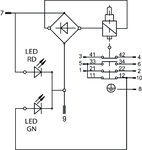
Connection examples
Teknik Veriler
Approvals


Electrical connection values
| Power consumption | 8 W |
| Display module | 24 V -15% ... +10% |
| Rated insulation voltage Ui | 50 V |
| Rated impulse voltage Uimp | 2.5 kV |
| Utilization category | |
| DC-13 | 4 A 24 V |
| AC-15 | 4 A 50 V |
| Short circuit protection according to IEC 60269-1 | 4A gG |
| Solenoid operating voltage | |
| AC/DC | 24 V -15% ... +10% |
| Solenoid duty cycle | 100 % |
| Switching voltage | |
| min. at 10 mA | 12 V |
| Switching current | |
| min. at 24 V | 1 mA |
| thermal rated current Ith | 4 A |
Mechanical values and environment
| Approach speed | max. 20 m/min |
| Approach direction | A |
| Connection type | |
| 1 x | Built-in connector BHA10 (9-pin + PE) |
| Number of door position NC contacts | 1 |
| Number of guard lock monitoring NO contacts | 1 |
| Number of guard lock monitoring positively driven contacts | 2 |
| Extraction force | 30 N |
| Actuation frequency | max. 1200 1/h |
| Actuating force | 35 N |
| Installation orientation | any |
| Insertion depth | 24.5 mm |
| Mechanical life | 1 x 10⁶ |
| Retention force | 20 N |
| Switching principle | Slow-action switching contact |
| Degree of protection | IP65 |
| Ambient temperature | -20 ... +70 °C |
| Material | |
| Contact | Silver alloy, gold flashed |
| Housing | Alloy - die-cast |
| Locking force Fmax | 3000 N |
| Locking force FZh | 2300 N |
| Guard locking principle | Closed-circuit current principle |
Characteristic values according to EN ISO 13849-1 and EN IEC 62061
| B10D | Mission time | |
|---|---|---|
| Monitoring of guard locking | 1.15x10⁷ | 20 y |
| Important! Values valid at DC-13 100 mA/24V | ||
| PL | Maximum SIL | Category | Mission time | |
|---|---|---|---|---|
| Control of guard locking | Depending on external control of guard locking | 20 y | ||
Miscellaneous
| C number | |
| C2398 | Special wiring, escape release long |
In combination with actuator ACTUATOR-S-GT-SN
| Overtravel | 5 mm |
Aksesuar


İndirme
Komple paket
Tüm önemli belgeleri tek bir tıklama ile indirin.
İçerik:
- Kullanım talimatları ve kullanım talimatlarına veya kısa talimatlara yapılan tüm eklemeler
- Kullanım talimatlarını tamamlayan tüm veri sayfaları
- Uygunluk beyanı
Tek Belgeler

Déclaration UE de conformité
Declaración de conformidad UE
EU-Konformitätserklärung
Dichiarazione UE di conformità

Déclaration UE de conformité
Declaración de conformidad UE
EU-Konformitätserklärung
Dichiarazione UE di conformità


Mode d’emploi Interrupteur de sécurité STA…
Manual de instrucciones Interruptor de seguridad STA…
Betriebsanleitung Sicherheitsschalter STA…


Diğer Belgeler


CAD Verileri

Sipariş verileri
| Sip. No. | 119366 |
| Makale adı | STA3A-2131A024L024BHA10C2398 |
| Ağırlık | 0,78kg |
| Gümrük sınıfı | 85365019000 |
| ECLASS | 27-27-26-03 Safety switch with guard control |