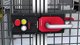
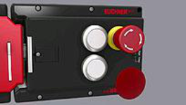
Interlocking set MGB-L0H-ARA..., with 2 pushbuttons, emergency stop, incl. label carrier, RC18
- Interlocking (without guard locking)
- Can be connected in series with other AR devices (e.g. CES-AR and CET-AR)
- Emergency stop according to ISO 13850
- 2 pushbuttons (illuminated, ye, wh)
- incl. adhesive labels
- With plug connector RC18
- Unicode
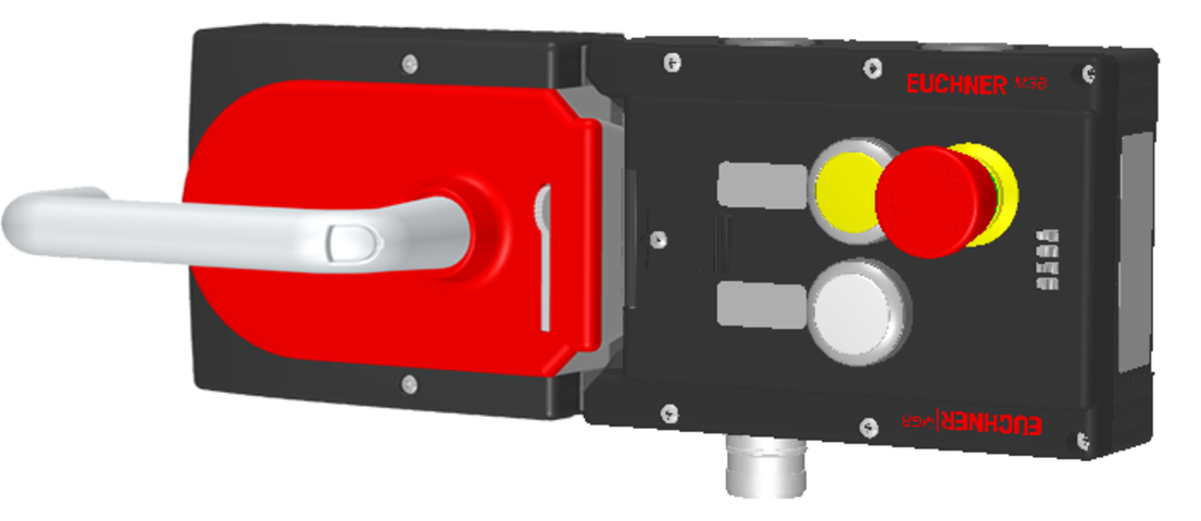
Açıklama
Guard locking type
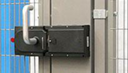
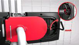
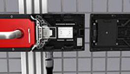
MGB-L0... | The bolt tongue in the handle module is moved into and out of the interlocking module by actuating the door handle. The door arm is not locked in the locked position. |
Door hinge
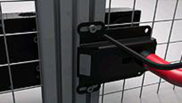
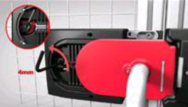
A mechanical door stop is permanently integrated into the evaluation module of the MGB. A marking on the stop makes adjustment easier.
LED indicator
The LED indicator indicates all important system and status information.
Monitoring outputs
OT | Bolt tongue inserted into the evaluation module |
OI | Diagnostics; there is a fault |
Emergency stop device
S1 | 2 positively driven contacts, emergency stop with turn-to-reset, not illuminated |
Pushbuttons
S2 | 1 NO contact, yellow, illuminated |
S3 | 1 NO contact, white, illuminated |
Adhesive labels
Devices with adhesive labels have pre-formed recesses. The adhesive labels enclosed (standard size 12.5 x 27 mm) can be affixed in these recesses.
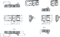
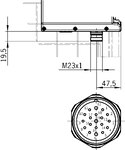

Dimensional drawings
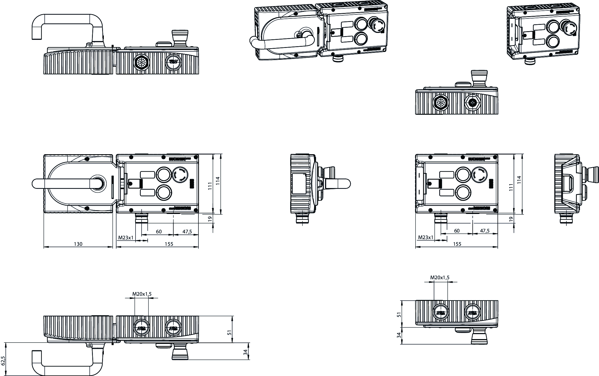
Dimensional drawings
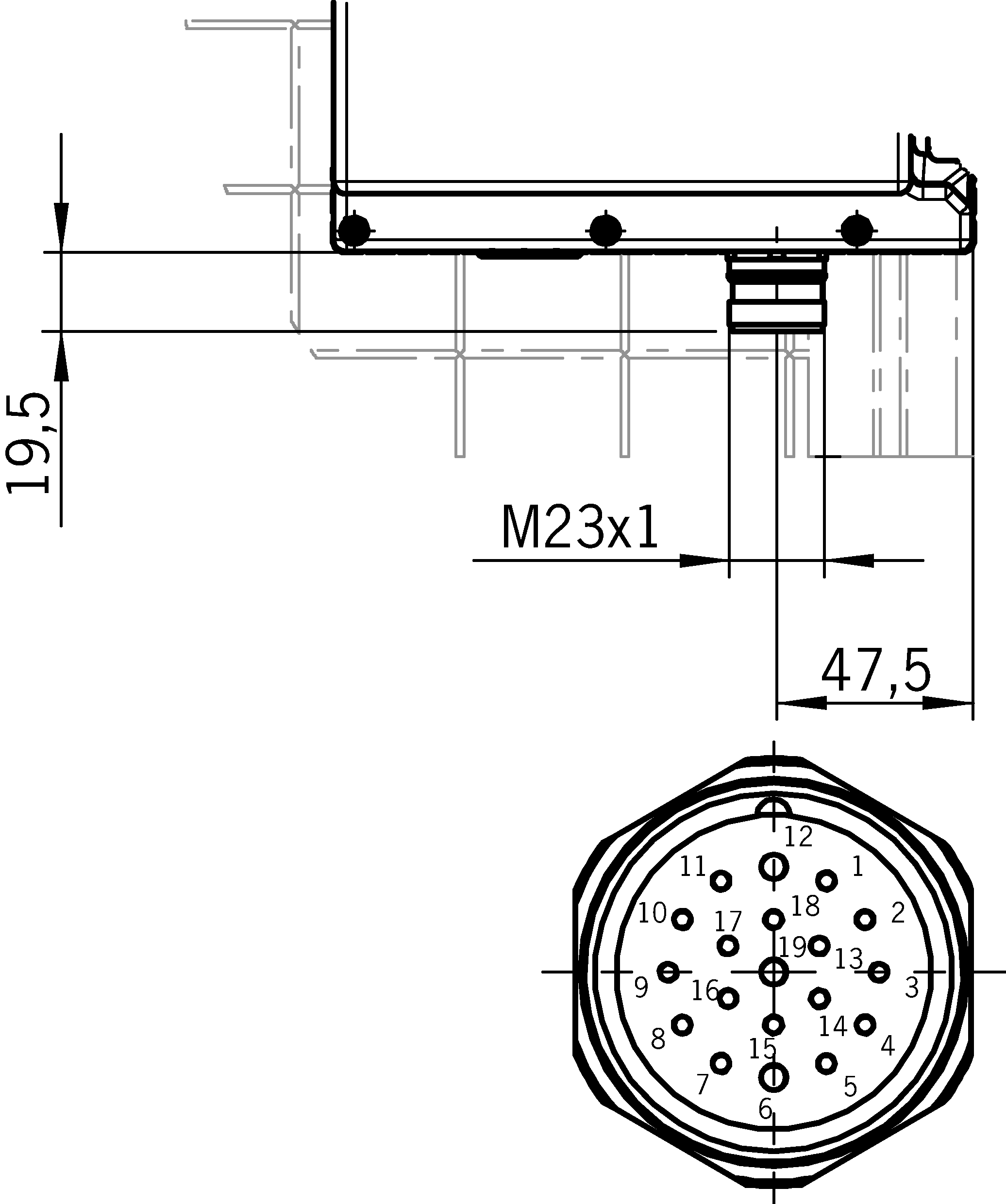
Connection examples

Teknik Veriler
Approvals


Handle modules MGB-H-AA1A1-L-106619 (Order no. 106619)

Mechanical values and environment
| Installation orientation | Door hinge DIN left |
| Degree of protection | IP65 |
| Ambient temperature | -20 ... +55 °C |
| Material | |
| Housing | Fiber glass reinforced plastic, nickel-plated die-cast zinc, stainless steel |
Miscellaneous
| Product version number | V3.0.0 |
Interlocking modules MGB-L0-ARA-AA2A1-S1-L-116302 (Order no. 116302)
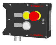
Operating and display elements
| Occupancy diagram | L1 |
| Item | Color | Extras | Note slide-in label | Version | Slide-in label | Switching element | Number | Designation1 | LED |
|---|---|---|---|---|---|---|---|---|---|
| 1 | Emergency stop | 2 PD | |||||||
| 2 | Yellow | Illuminated pushbutton | 1NO | ||||||
| 3 | white | Illuminated pushbutton | 1NO |
Electrical connection values
| Rated insulation voltage Ui | 30 V |
| Rated impulse withstand voltage Uimp | 1.5 kV |
| Discrepancy time | |
| between FO1A and FO1B | max. 10 ms |
| Utilization category | |
| DC-13 | 24 V 200 mA (Caution: outputs must be protected with a free-wheeling diode in case of inductive loads.) |
| Risk time according to EN 60947-5-3 | max. 350 ms |
| Risk time according to EN 60947-5-3, extension for each additional device | max. 5 ms |
| Safety class | III |
| Transponder coding | Unicode |
| Degree of contamination (external, according to EN 60947-1) | 3 |
| Controls and indicators | |
| Breaking capacity | max. 0.25 W |
| Switching voltage | UA V |
| Switching current | 1 ... 10 mA |
| LED power supply | 24 V DC |
| Emergency stop | |
| Breaking capacity | max. 0.25 W |
| Switching voltage | 5 ... 24 V |
| Switching current | 1 ... 100 mA |
| LED power supply | 24 V DC |
| Monitoring outputs OD, OT, OL, OI | |
| Output type | Semiconductor outputs, p-switching, short circuit-proof |
| Output voltage | UA-2V ... UA V DC (Value at a switching current of 50mA without taking into account the cable lengths) |
| Output current | max. 50 mA |
| Safety outputs FO1A, FO1B | |
| Output type | Semiconductor outputs, p-switching, short circuit-proof |
| Output voltage | |
| UFO1A /UFO1B LOW | 0 ... 1 V DC |
| UFO1A /UFO1B HIGH | UB-2V ... UB V DC (Value at a switching current of 50mA without taking into account the cable lengths) |
| Output current | |
| per safety output FO1A / FO1B | 1 ... 200 mA |
| Test pulse duration | max. 1 ms |
| Test pulse interval | min. 100 ms |
| Power supply UA | |
| Operating voltage DC | |
| UA | 24 V DC -15% ... +10% ((reverse polarity protected, regulated, residual ripple<5%, PELV)) |
| Current consumption | |
| IUA | max. 10 mA ((with no load on outputs OD, OT, OL, OI)) |
| Power supply UB | |
| Operating voltage DC | |
| UB | 24 V DC -15% ... +10% ((reverse polarity protected, regulated, residual ripple<5%, PELV)) |
| Current consumption | |
| IUB | max. 80 mA ((no load on outputs)) |
Mechanical values and environment
| Connection type | Plug connector RC18 (X6) |
| Installation orientation | Door hinge DIN left |
| Switching frequency | 0.25 Hz |
| Mechanical life | |
| in case of use as door stop, and 1 Joule impact energy | 0.1 x 10⁶ |
| 1 x 10⁶ | |
| Degree of protection | IP65 |
| Ambient temperature | |
| with UB = 24 V DC | -20 ... +55 °C |
| Material | |
| Housing | Fiber glass reinforced plastic; nickel-plated die-cast zinc; stainless steel |
Miscellaneous
| Slide-in label | |||||||
| |||||||
| Product version number | V4.0.0 | ||||||
Bileşenler
MGB-H-AA1A1-L-106619
Handle module MGB-H-...
- Intelligent bolt tongue
- Lockout mechanism
- Door handle

MGB-L0-ARA-AA2A1-S1-L-116302
Interlocking module MGB-L0-ARA..., with 2 pushbuttons, emergency stop, incl. label carrier, RC18
- Interlocking (without guard locking)
- Can be connected in series with other AR devices (e.g. CES-AR and CET-AR)
- Emergency stop according to ISO 13850
- 2 pushbuttons (illuminated, ye, wh)
- incl. adhesive labels
- With plug connector RC18
- Unicode
Aksesuar
İndirme
Komple paket
Tüm önemli belgeleri tek bir tıklama ile indirin.
İçerik:
- Kullanım talimatları ve kullanım talimatlarına veya kısa talimatlara yapılan tüm eklemeler
- Kullanım talimatlarını tamamlayan tüm veri sayfaları
- Uygunluk beyanı
Tek Belgeler


Diğer Belgeler


CAD Verileri
Sipariş verileri
| Sip. No. | 110958 |
| Makale adı | MGB-L0H-ARA-L-110958 |
| Ağırlık | 2,086kg |
| Gümrük sınıfı | 85371098 |
| ECLASS | 27-27-24-03 Safety-related transponder switch |


